Aria Automation: Going from NSX-T Load Balancer to AVI Load Balancer

Hello Everyone!

On today’s post, we’re going to talk about the newly released feature in Aria Automation 8.16.1 which is the native integration with the AVI Load Balancer (also called Advanced Load Balancer, and from now on this post, ALB) by using a NSX-T Load Balancer as an example and starting point.

The goal of this post will be for you to be able to operate with the AVI Load Balancer from Aria Automation in the same way that you can do today with the NSX-T Load Balancer.

Initial Setup

For the initial setup and cloud account configuration, you can follow https://docs.vmware.com/en/VMware-Aria-Automation/8.16/Using-Automation-Assembler/GUID-190DD085-2F1B-4888-A7F1-DAA8D5A8380E.html

On that document, in addition to a list of steps, you will also see what permissions are needed by the Aria Automation user that will be interacting with ALB.

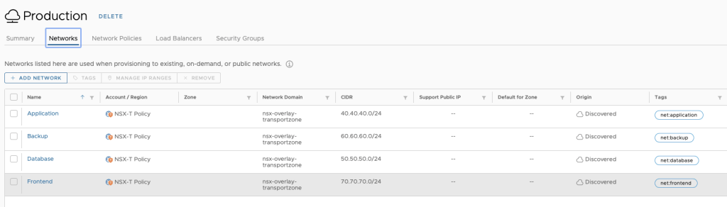
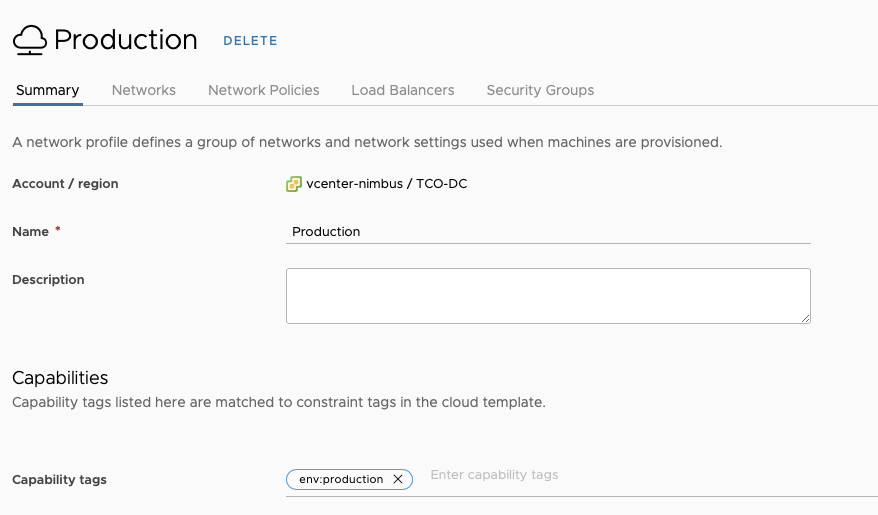
It is important to configure these Cloud Accounts with the same capability tags that the vCenters in the same location (and that will be hosting these resources) have.

While there is a native ‘association’ between NSX-T and vCenter, that concept does not currently exist with ALB. If you plan on having more than one ALB Cloud Account in your Aria Automation instance, and you plan to leverage the allocation helper construct (which we will talk about later) make sure the tagging is in place.

This will create a Cloud Zone in Aria Automation as well. Make sure you are adding this Cloud Zone to the projects you plan to consume (as stated in the documentation above). This will all come into play later.

Assumptions on the ALB side

For the purposes of this blog post, I’m going to take the following assumptions on the ALB configuration side, which need to be in place for the integration to work.

  • There is a NSX-T Cloud Configured with the same vCenter and NSX-T account that you will be using in Aria Automation
  • There is at least one IPAM profile assigned to the NSX-T cloud with at least one usable VIP network profile configured for allocating VIP IPs
    • This VIP network profile name matches the network name in NSX-T
  • There is a Service Engine group correctly configured

Now that everything is set up on the Aria Automation side (and ALB side) let’s move on to our use case!

NSX-T Template

Let’s take a look at the following NSX-T LB YAML Code

LB:
    type: Cloud.NSX.LoadBalancer
    properties:
      routes:
        - protocol: HTTP
          port: 80
          instancePort: 80
          instanceProtocol: HTTP
          algorithm: ROUND_ROBIN
          healthCheckConfiguration:
            healthyThreshold: 2
            unhealthyThreshold: 3
            protocol: HTTP
            intervalSeconds: 15
            urlPath: /
            httpMethod: GET
            port: 80
          persistenceConfig:
            type: COOKIE
            cookieMode: INSERT
            cookieName: CK-${uuid()}
            cookieGarble: true
            maxAge: 3600
            maxIdle: 600
        - protocol: TCP
          port: 1000
          instancePort: 1000
          instanceProtocol: TCP
          algorithm: LEAST_CONNECTION
          healthCheckConfiguration:
            healthyThreshold: 2
            unhealthyThreshold: 3
            protocol: TCP
            intervalSeconds: 15
            port: 1000
          persistenceConfig:
            type: SOURCE_IP
            ipPurge: true
            maxIdle: 60
      network: ${resource.Cloud_NSX_Network_1.id}
      loggingLevel: WARNING
      instances: ${resource.Cloud_vSphere_Machine_1[*].id}

What do we have?

  • Two virtual servers. One with TCP Port 1000, and another one with HTTP Port 80. Load Balancer Algorithm used for each of them is different
  • Each virtual server has it’s own specific health check configuration as well as an application persistence configuration
  • Load Balancer is using an existing NSX network in the deployment
  • Load Balancer is taking the VM instances in the deployment as their pool members. Since VMs have a dynamic count, it is specified in that way in the assignment.

So how do we recreate this using ALB?

ALB Objects

Let’s first take a look at all the ALB objects that are available to use -> From https://docs.vmware.com/en/VMware-Aria-Automation/8.16/Using-Automation-Assembler/GUID-4844BFD9-18A5-4F8D-A53F-059DDE5DB0FF.html

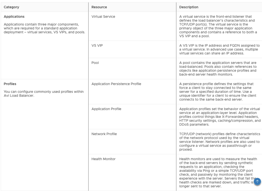
This is how these resources look in the Canvas:

In addition to this, we’re going to need to use the Allocation Helper for the cloud zone, which is also an available resource in the canvas.

Now that we have all of this, what does our NSX-T example translate to, with regards to objects?

We’re going to need:

  • One VS VIP object for IP allocation (either static or dynamic)
  • One Pool object per route
  • One Virtual Service object per route
  • One Monitor object per each individual health check configuration
  • One Application Persistence object per each individual persistence configuration
  • One Cloud Zone Helper object for placement

I know this sounds like a handful, but we will explain how to build each of these objects below. ALB provides much greater flexibility with regards to features, but that comes with the tradeoff of complexity.

It might take us longer to build what looked simpler in NSX-T, but once we’re over that hurdle, the amount of new possibilities is much greater!

Building the ALB Objects

While I’m going to explain each how to build each object here, there is a resource that’s invaluable for building all of this, which is the Swagger documentation of the ALB API.

You can access it by going to https://your_avi_controller_fqdn/swagger/#/

In the swagger documentation, you will be able to see each object’s schema model, as well as examples of creation. You might need to tweak and modify some of it to be able to use it in Aria Automation, but with some trial and error, success is very likely!

I will go about these objects in order by dependency – that means, an object has to be created first (it has to exist), to then be referenced by another object.

Cloud Zone Helper Object

This object will be used to apply constraint tags – In this example, I will match the tags that my VM objects have, so that there is matching with the vCenter – This one is pretty self explanatory, and it will be referenced by other objects

Allocations_CloudZone_1:
    type: Allocations.CloudZone
    properties:
      accountType: avilb
      constraints:
        - tag: site:${input.site}
        - tag: securityzone:${input.securityZone}
        - tag: az:${input.availabilityZone}

VS VIP Object

 VSVIP_1:
    type: Idem.AVILB.APPLICATIONS.VS_VIP
    properties:
      name: VSVIP_${env.deploymentName}
      description: Managed by Aria Automation
      vrf_context_ref: T1-W1-Gateway-DR-01
      tier1_lr: /infra/tier-1s/20f6q214-e8b3-4cb3-aaeb-6c07639ada23
      account: ${resource.Allocations_CloudZone_1.selectedCloudAccount.name}
      vip:
        - vip_id: 0
          auto_allocate_ip: true
          auto_allocate_ip_type: V4_ONLY
          enabled: true
          ipam_network_subnet:
            network_ref: ${resource.Cloud_NSX_Network_1.resourceName}

Object Explanation:

  • VSVIP requires a name – This is the name that you will see in the ALB console – you can set this to whatever name you want, but it makes sense to tie this to the deployment name so that you can identify it
  • description can also be anything
  • vrf_context_ref would be the name of the context ref in your NSX-T Cloud in ALB
  • tier1_lr is the path to the T1 Gateway in your NSX-T instance – this uses the relative path in the NSX-T API as it is not an ALB Object:
    • Note: this might change in future versions and might not be needed
  • account is the ALB cloud account that you’re going to use – here is where you reference the Cloud Zone Helper created before
  • vip is it’s own object, with the following properties
    • Since we’re only using a single VIP, vip_id would be 0
    • auto_allocate_ip is set to true because we want dynamic IP
    • auto_allocate_ip_type is set to V4_ONLY because we’re doing IPV4
    • enabled is set to true because we are enabling this VS VIP as we create it
    • ipam_network_subnet is an object with a network_ref that maps to a VIP network profile in ALB
      • Since this should match to a NSX-T network, we can use the network name in the deployment as an identifier
      • This would be different if you were using a dedicated VIP segment. If that is the case, you can reference a specific VIP network profile name by name instead of using the name of the network resource in the deployment

Monitor Objects

For this deployment, we will have two monitor objects – one for each health check configuration

MONITOR_1:
    type: Idem.AVILB.PROFILES.HEALTH_MONITOR
    properties:
      name: MONITOR_${env.deploymentName}_1
      account: ${resource.Allocations_CloudZone_1.selectedCloudAccount.name}
      monitor_port: '80'
      type: HEALTH_MONITOR_HTTP
      successful_checks: 2
      failed_checks: 3
      send_interval: 15
      http_request: GET /
  MONITOR_2:
    type: Idem.AVILB.PROFILES.HEALTH_MONITOR
    properties:
      name: MONITOR_${env.deploymentName}_2
      account: ${resource.Allocations_CloudZone_1.selectedCloudAccount.name}
      monitor_port: '1000'
      type: HEALTH_MONITOR_TCP
      successful_checks: 2
      failed_checks: 3
      send_interval: 15

Object Explanation:

  • These objects also require names. To maintain consistency, we will be using the deployment name as an identifier
    • Important – Since there will be more than one monitor, we’re using _NUMBER as an identifier as well. Then we can use the same numbering to map this to other objects (like Virtual Services, Pools or Profiles)
    • You can also see that I’m using the same numbering for the objects within the YAML. This helps maintain consistency and makes it easier to understand what maps to what.
  • account follows the same logic as in the VS VIP (and all the objects) – mapped to the Cloud Zone Helper object
  • monitor_port is the port that is being monitored
  • type is the monitor type – in this case, we have a HTTP and a TCP monitor
  • successful_checks, failed_checks and send_interval are self explanatory
  • http_request (which only shows up in the HTTP monitor) would be the method to use, and to what URL, in this case, we’re doing a GET to /

Application Persistence Objects

For this deployment, we will have two Application Persistence objects, one per application persistence configuration

 PERSISTENCE_PROFILE_1:
    type: Idem.AVILB.PROFILES.APPLICATION_PERSISTENCE_PROFILE
    properties:
      name: PERSISTENCE_${env.deploymentName}_1
      account: ${resource.Allocations_CloudZone_1.selectedCloudAccount.name}
      persistence_type: PERSISTENCE_TYPE_CLIENT_IP_ADDRESS
      ip_persistence_profile:
        ip_mask: 0
        ip_persistent_timeout: 60
 PERSISTENCE_PROFILE_2:
    type: Idem.AVILB.PROFILES.APPLICATION_PERSISTENCE_PROFILE
    properties:
      name: PERSISTENCE_${env.deploymentName}_2
      account: ${resource.Allocations_CloudZone_1.selectedCloudAccount.name}
      persistence_type: PERSISTENCE_TYPE_HTTP_COOKIE
      http_cookie_persistence_profile:
        cookie_name: CK_${env.deploymentName}_2
        timeout: 3600
        is_persistent_cookie: false

Object Explanation

  • Like every object, they need a name – following the same structure as the other objects
  • account also follows the same structure
  • persistence_type will depend on the type of persistence. We have one config for Source IP and one config for Cookie
  • The object with the properties will be dependent on the persistence_type
    • If you’re using Source IP persistence, the object will be ip_persistence_profile
      • ip_mask is the mask to be applied to the client IP. This is 0 because we’re not applying a mask
      • ip_persistent_timeout is the length of time before expiring the client’s persistence to a server, after its connections have been closed
    • If you’re using Cookie Persistence, the object will be http_cookie_persistence_profile
      • cookie_name is required and we can use the same naming structure as we use for the rest of the objects. I’m also making the number match to the number in the YAML resource for easier undertanding
      • timeout is the maximum lifetime of any session cookie
      • is_persistent_cookie controls the usage of the cookie as a session cookie even after the timeout, if the session is still open. With false, we’re allowing for this to happen

Pool Objects

For this deployment, we will have two Pool objects, one per route

POOL_1:
    type: Idem.AVILB.APPLICATIONS.POOL
    properties:
      name: POOL_${env.deploymentName}_1
      account: ${resource.Allocations_CloudZone_1.selectedCloudAccount.name}
      tier1_lr: /infra/tier-1s/20f6a214-e8b3-4bb3-aaeb-6c06639ada23
      description: Managed by Aria Automation
      default_server_port: '80'
      health_monitor_refs:
        - ${resource.MONITOR_1.name}
      lb_algorithm: LB_ALGORITHM_ROUND_ROBIN
      servers: '${map_by(resource.Cloud_vSphere_Machine_1[*].address, address => {"ip": {"addr": address, "type" : "V4"}})}'
      application_persistence_profile_ref: /api/applicationpersistenceprofile/${resource.PERSISTENCE_PROFILE_1.resource_id}
POOL_2:
    type: Idem.AVILB.APPLICATIONS.POOL
    properties:
      name: POOL_${env.deploymentName}_2
      account: ${resource.Allocations_CloudZone_1.selectedCloudAccount.name}
      tier1_lr: /infra/tier-1s/20f6a214-e8b3-4bb3-aaeb-6c06639ada23
      description: Managed by Aria Automation
      default_server_port: '1000'
      health_monitor_refs:
        - ${resource.MONITOR_2.name}
      lb_algorithm: LB_ALGORITHM_LEAST_CONNECTIONS
      servers: '${map_by(resource.Cloud_vSphere_Machine_1[*].address, address => {"ip": {"addr": address, "type" : "V4"}})}'
      application_persistence_profile_ref: /api/applicationpersistenceprofile/${resource.PERSISTENCE_PROFILE_2.resource_id}

Object Explanation

  • name, account and description follow the same structure as the other objects
  • tier1_lr is used in the same way as in the VS VIP object
  • default_server_port is the default server port (would map to the internal port in the NSX-T Load Balancer)
  • health_monitor_refs is an array of monitor references. Since our monitors are different, we are only going to use one item in the array, and this reference maps to the numbering used in the monitors
    • This is why we kept numbering consistent – so MONITOR_1 maps to POOL_1 and MONITOR_2 maps to POOL_2
  • servers maps to the servers in the deployment – the syntax uses map_by to allow for clustering as well as both attributes needed by the ip object, which are addr and type
  • application_persistence_profile_ref maps to the application persistence object defined before
    • Same scenario with the monitor – We keep numbering consistent so PERSISTENCE_PROFILE_1 maps to POOL_1 and PERSISTENCE_PROFILE_2 maps to POOL_2

Virtual Services Objects

For this deployment, we will have two Virtual Services objects, one per route

VIRTUALSERVICE_1:
    type: Idem.AVILB.APPLICATIONS.VIRTUAL_SERVICE
    properties:
      name: VS_${env.deploymentName}_1
      account: ${resource.Allocations_CloudZone_1.selectedCloudAccount.name}
      vrf_context_ref: T1-W1-Gateway-DR-01
      enabled: true
      services:
        - enable_ssl: false
          port: '80'
      traffic_enabled: true
      vsvip_ref: /api/vsvip/${resource.VSVIP_1.resource_id}
      pool_ref: /api/pool/${resource.POOL_1.resource_id}
      application_profile_ref: /api/applicationprofile?name=System-HTTP
      network_profile_ref: /api/networkprofile?name=System-TCP-Proxy
 VIRTUALSERVICE_2:
    type: Idem.AVILB.APPLICATIONS.VIRTUAL_SERVICE
    properties:
      name: VS_${env.deploymentName}_2
      account: ${resource.Allocations_CloudZone_1.selectedCloudAccount.name}
      vrf_context_ref: T1-W1-Gateway-DR-01
      enabled: true
      services:
        - enable_ssl: false
          port: '1000'
      traffic_enabled: true
      vsvip_ref: /api/vsvip/${resource.VSVIP_1.resource_id}
      pool_ref: /api/pool/${resource.POOL_2.resource_id}
      application_profile_ref: /api/applicationprofile?name=System-L4-Application
      network_profile_ref: /api/networkprofile?name=System-TCP-Fast-Path
  

Object Explanation

  • name and account follow the same structure as in the other objects
  • vrf_context follows the same structure as in the VS VIP object
  • enabled is set to true because we want this service to be enabled
  • services is an array – but since we’re mapping this to a single pool, we will only have one service in the virtual service
    • We’re using the same port as the internal port, and enable_ssl is set to false
  • traffic_enabled is set to true to allow for traffic
  • vsvip_ref references the VS VIP object previously created – since there is a single VSVIP object, both virtual services will reference it
  • pool_ref references the pool that has the members for this service. Using the same numbering strategy as before, VIRTUALSERVICE_1 references POOL_1 and the same thing with number 2
  • application_profile_ref will vary based on the protocol – To align with NSX-T LB:
    • for HTTP it will reference System-HTTP
    • for TCP it will reference System-L4-Application
  • network_profile_ref will also vary based on the protocol – To align with NSX-T LB
    • for HTTP it will reference System-TCP-Proxy
    • for TCP it will reference System-TCP-Fast-Path

Complete object

Adding up everything we created before, we end up with this YAML code!

Allocations_CloudZone_1:
    type: Allocations.CloudZone
    properties:
      accountType: avilb
      constraints:
        - tag: site:${input.site}
        - tag: securityzone:${input.securityZone}
        - tag: az:${input.availabilityZone}
VSVIP_1:
    type: Idem.AVILB.APPLICATIONS.VS_VIP
    properties:
      name: VSVIP_${env.deploymentName}
      description: Managed by Aria Automation
      vrf_context_ref: T1-W1-Gateway-DR-01
      tier1_lr: /infra/tier-1s/20f6q214-e8b3-4cb3-aaeb-6c07639ada23
      account: ${resource.Allocations_CloudZone_1.selectedCloudAccount.name}
      vip:
        - vip_id: 0
          auto_allocate_ip: true
          auto_allocate_ip_type: V4_ONLY
          enabled: true
          ipam_network_subnet:
            network_ref: ${resource.Cloud_NSX_Network_1.resourceName}
MONITOR_1:
    type: Idem.AVILB.PROFILES.HEALTH_MONITOR
    properties:
      name: MONITOR_${env.deploymentName}_1
      account: ${resource.Allocations_CloudZone_1.selectedCloudAccount.name}
      monitor_port: '80'
      type: HEALTH_MONITOR_HTTP
      successful_checks: 2
      failed_checks: 3
      send_interval: 15
      http_request: GET /
  MONITOR_2:
    type: Idem.AVILB.PROFILES.HEALTH_MONITOR
    properties:
      name: MONITOR_${env.deploymentName}_2
      account: ${resource.Allocations_CloudZone_1.selectedCloudAccount.name}
      monitor_port: '1000'
      type: HEALTH_MONITOR_TCP
      successful_checks: 2
      failed_checks: 3
      send_interval: 15
POOL_1:
    type: Idem.AVILB.APPLICATIONS.POOL
    properties:
      name: POOL_${env.deploymentName}_1
      account: ${resource.Allocations_CloudZone_1.selectedCloudAccount.name}
      tier1_lr: /infra/tier-1s/20f6a214-e8b3-4bb3-aaeb-6c06639ada23
      description: Managed by Aria Automation
      default_server_port: '80'
      health_monitor_refs:
        - ${resource.MONITOR_1.name}
      lb_algorithm: LB_ALGORITHM_ROUND_ROBIN
      servers: '${map_by(resource.Cloud_vSphere_Machine_1[*].address, address => {"ip": {"addr": address, "type" : "V4"}})}'
      application_persistence_profile_ref: /api/applicationpersistenceprofile/${resource.PERSISTENCE_PROFILE_1.resource_id}
POOL_2:
    type: Idem.AVILB.APPLICATIONS.POOL
    properties:
      name: POOL_${env.deploymentName}_2
      account: ${resource.Allocations_CloudZone_1.selectedCloudAccount.name}
      tier1_lr: /infra/tier-1s/20f6a214-e8b3-4bb3-aaeb-6c06639ada23
      description: Managed by Aria Automation
      default_server_port: '1000'
      health_monitor_refs:
        - ${resource.MONITOR_2.name}
      lb_algorithm: LB_ALGORITHM_LEAST_CONNECTIONS
      servers: '${map_by(resource.Cloud_vSphere_Machine_1[*].address, address => {"ip": {"addr": address, "type" : "V4"}})}'
      application_persistence_profile_ref: /api/applicationpersistenceprofile/${resource.PERSISTENCE_PROFILE_2.resource_id}
VIRTUALSERVICE_1:
    type: Idem.AVILB.APPLICATIONS.VIRTUAL_SERVICE
    properties:
      name: VS_${env.deploymentName}_1
      account: ${resource.Allocations_CloudZone_1.selectedCloudAccount.name}
      vrf_context_ref: T1-W1-Gateway-DR-01
      enabled: true
      services:
        - enable_ssl: false
          port: '80'
      traffic_enabled: true
      vsvip_ref: /api/vsvip/${resource.VSVIP_1.resource_id}
      pool_ref: /api/pool/${resource.POOL_1.resource_id}
      application_profile_ref: /api/applicationprofile?name=System-HTTP
      network_profile_ref: /api/networkprofile?name=System-TCP-Proxy
 VIRTUALSERVICE_2:
    type: Idem.AVILB.APPLICATIONS.VIRTUAL_SERVICE
    properties:
      name: VS_${env.deploymentName}_2
      account: ${resource.Allocations_CloudZone_1.selectedCloudAccount.name}
      vrf_context_ref: T1-W1-Gateway-DR-01
      enabled: true
      services:
        - enable_ssl: false
          port: '1000'
      traffic_enabled: true
      vsvip_ref: /api/vsvip/${resource.VSVIP_1.resource_id}
      pool_ref: /api/pool/${resource.POOL_2.resource_id}
      application_profile_ref: /api/applicationprofile?name=System-L4-Application
      network_profile_ref: /api/networkprofile?name=System-TCP-Fast-Path

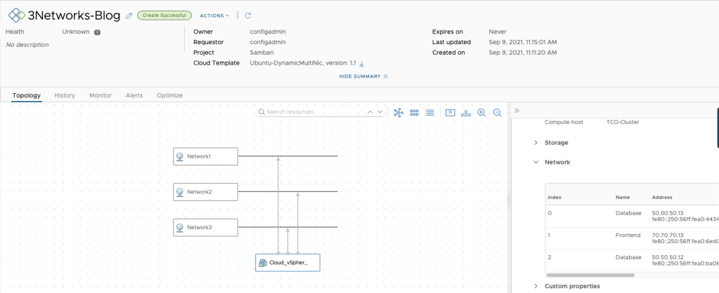
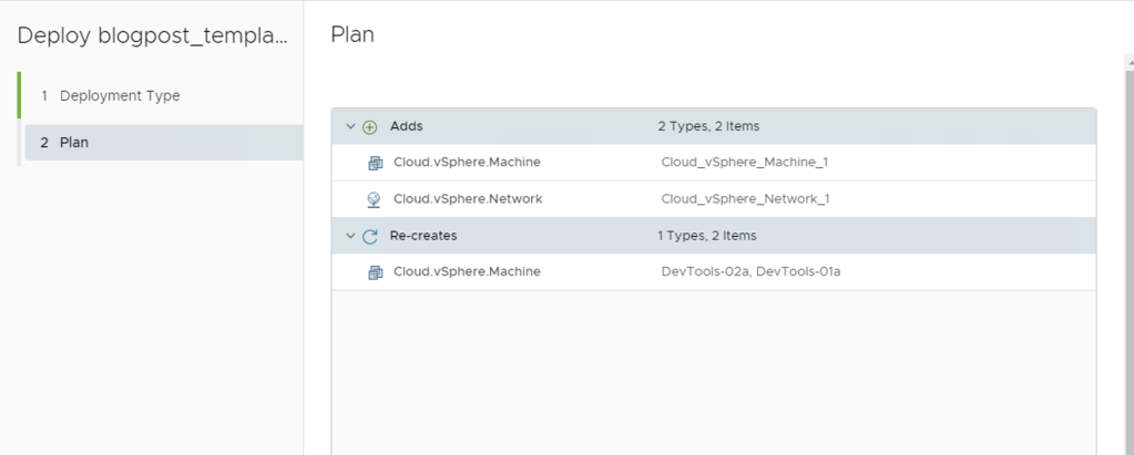
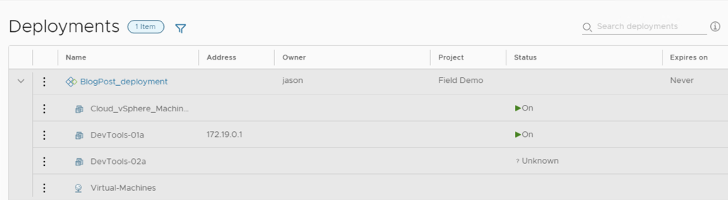
Adding this code to a blueprint that already has a VM Object and a Network Object will let us do a deployment that will look like this!

Hooray!!!!


Some Caveats and Final Thoughts

  • Currently, the only supported way to update ALB objects using vRA is via Iterative Updating – this means, applying a new YAML code to the deployment
    • This can be done by changing the blueprint and then updating the deployment, or by using blueprint-requests API to send new YAML code to the deployment
  • Official documentation (linked above) and the Swagger are your best friends – There are many more options that can be configured based on your business needs!
  • The official blog by Scott McDermott also has some examples that could be useful! -> https://blogs.vmware.com/management/2024/02/deploy-avi-load-balancer-with-aria-automation-templates.html

I hope you find this useful! If you do, please leave a comment, and don’t hesitate to reach out with any questions!

VMware Explore 2023 Session

Hello Everyone!

I wanted to make this post to invite you to the session I’m going to be presenting at VMware Explore 2023 in Las Vegas, Aug 21-24, with my colleague Pontus Rydin!

The title of the session is “Lessons Learned from the Most Complex VMware Aria Automation 7 to 8 Migration to Date”

In this session we will go over an extremely interesting customer scenario with regards to migration, and how we managed to get to the other side successfully. A lot of requirement analysis, thinking outside of the box, developing process, code, testing, and coming up with creative ideas to a problem that seemed impossible.

We are going to be presenting this session twice!

I’m really looking forward to seeing you all there. It’s going to be a blast.

Automating the movement of T1 Gateways across Edge Clusters in NSX-T

Hello Everyone!

It’s been a while since I wrote my last post. Many many things happened both in my life as well as work. Not an excuse for my lack of posting, but I do plan to get back to blogging more consistently in the year 2023.

What do we have here today?

In today’s edition, I bring you I script I wrote to move T1 gateways across Edge Clusters in NSX-T. It can programmatically move hundreds of T1s in a couple minutes.

LINK TO THE SCRIPT

Why would I need to move my T1 Gateways across Edge Clusters?

There are multiple scenarios that would trigger the need to move / evacuate T1 gateways to a different Edge Cluster. The most common are:

  • During a NSX-V to NSX-T migration, Migration Coordinator will, by default, put all T1 gateways in the same Edge Cluster that is being used for the T0s. In an architecture where there is a dedicated Edge Cluster for T0 ECMP / Uplink, and Edge Cluster/s used for T1 Stateful services (such as load balancing) this is not ideal.
  • A 10-node XL Edge Cluster can only host up to 400 Small load balancers. Going over this limit will require to build an additional Edge Cluster. vRA can only deploy Load Balancers to a single Edge Cluster at any given time per any given Network Profile. If we reach the limit, we either create the new cluster and change the network profile to the new cluster, or, we can migrate the current T1s to the new cluster, and keep using the one we previously had in the network profile
  • Rebalancing of T1 Gateways across Edge Cluster for maintain a similar number of T1s across all edge clusters.

How do I use this script?

In the initial comments of the script there is an explanation of the usage

<################################################
Move (T1s) across edge clusters
Author: @ldelorenzi - Jan 23  
Usage:
moveT1s.ps1 -nsxUrl <NSX Manager URL (with HTTPS)) -sourceClusterName <Edge Cluster Name> -destinationClusterName <Edge Cluster Name> -execute <$true/$false> -count <count of load balancers to move>
Credentials will be asked at the beginning of the run
################################################>

To dive a little bit deeper into these parameters:

  • nsxUrl: The NSX-T manager we will be hitting with this script. Including HTTPS
  • sourceClusterName: The name of the Edge Cluster that hosts the T1 Gateways we want to move
  • destinationClusterName: The name of the Edge Cluster that will receive the T1 Gateways from the source cluster
  • execute: By default, the execute flag is set to false. This means that if no value is used in the script, it will default to false. If execute is false, the script will only show us what T1s were found in the source cluster and therefore will be moved to the destination cluster
  • count: If you don’t want to fully evacuate the cluster and you want to just move some T1s from source cluster to destination cluster, you can set a value for the count parameter and that will limit the amount of T1s that are moved.

Interesting things about the Script

  • If you look at the code you will see that I built my own wrapper for invoke-RestMethod called restCall – this function has logging included as well as retries. If you’re going to have a lot of REST API calls in your scripts, it could make sense to include something like this!
  • The ‘movement’ of T1 Gateways actually involves patching the T1 SR object with its new cluster ID. The script finds the Edge Cluster IDs using the names provided at the beginning of the run. This makes it friendlier for users / admins since just the name can be used instead of having to find the id.

Closing Note

I hope you enjoy this post and make use of this script in your environments. If you liked this, please share it!

Until next time!

SaltStack Config Enterprise Install, Multi-Master setup and Git repo configuration!

Hello Everyone! On today’s post, I’m going to do a step by step walkthrough of a SaltStack Config (from now on, SSC) enterprise install. The SSC enterprise install is meant to be used in production-grade environments, and can handle up to 5000 Salt Minions per master!

I will also cover how scale-out the deployment and add a new Salt Master (in a cluster configuration) to the deployment after it is finished.

In addition to this, I will cover how to configure a Git repo as a shared storage across masters.

Lastly, I will cover how to prepare a vRA Cloud Template to install the Salt Minion, configure it to use multiple masters, and run a Salt State on the deployment!

Let’s start! Buckle up!

Architecture

This deployment is going to have:

  • One VM for PostgreSQL and Redis – Required for persistent & in-memory database components. These two components could be also separated across two different VMs (and configured in HA, but only for manual failover).
  • One VM for RaaS (Responder as a Service) – This is going to be the GUI of SSC. The RaaS component can also be deployed in a cluster mode using an external load balancer, but I’m going to use a single one in this post.
  • Two VMs, one for each Salt Master, that will form a cluster. The secondary master and the cluster will be generated after the initial deployment.
  • Both Salt Masters will be configured to use a Github repository.

All VMs are running Centos 7 as the operating system.

Architecture

This is what my servers look like, from a vSphere point of view.

VMs

List of Steps

What do you need to do to carry out this deployment?

The first list of steps is based on this LINK, which is the ‘Installing and Configuring Saltstack Config’ Official Documentation from VMware.

  • Prepare the template for the VMs (you can prepare each VM separately but there are common items across all VMs)
  • Deploy the 4 VMs (take note of the IP addresses)
  • Prepare the VM that will become the Primary Salt Master
  • Prepare the VMs that will only be Salt Minions (the PostgreSQL / Redis & the RaaS)
  • Download & Copy the SSC installer to the Primary Master
  • Copy and edit the top state files
  • Edit the SSC settings Pillar file
  • Apply the highstates to the nodes
  • Install the License Key
  • Install and configure the Master Plugin on the Primary Salt Master
  • Log in for the first time and change the default credentials
  • Accept the Primary Salt Master key
  • Optional: Configure Backup for files (if not using a complete backup solution), Set up custom SSL certificates, SSO. (won’t be doing this as a part of this post) -> Link1, Link2, Link3

At this point, you’re going to have a functional SSC enterprise install, but you will only have a single master node. You still need to configure the Secondary Master, the cluster, and the repository!

The second list of steps is based on multiple sources and testing, since there isn’t a single source of information to configure all of this. Which is why I’m attempting to write this and condense it! I will be adding links throughout the steps.

  • Prepare the VM that will become the Secondary Salt Master
  • Copy the SSC installer to the Secondary Master
  • Prepare all the other minions to use Primary and Secondary Salt Masters
  • Copy Primary master key to the Secondary Master
  • Edit the RaaS configuration file (master plugin) on the primary master to add the Cluster ID
  • Install and configure the Master Plugin in the Secondary Master
  • Edit the RaaS configuration file (master plugin) on the Secondary Master to add the Cluster ID
  • Start Salt-Master on the Secondary Master and accept the Secondary Salt Master key
  • Install GitPython on both Salt Masters
  • Configure the GitFS filesystem and Github repository
  • Configure a Cloud Template on vRA to install the Salt Minion and configure the two masters
  • Create a Job using the Salt State hosted in Github
  • Run the Job!

Don’t be scared! I will be explaining every single step so you’re also able to have a successful deployment. Let’s start!

1: Prepare the template for VMs

You need to install OpenSSL, EPEL, and two libraries for Python (cryptography and OpenSSL) so this is what you need to run:

sudo yum install openssl -y
sudo yum install epel-release -y
sudo yum install python36-cryptography -y 
sudo yum install python36-pyOpenSSL -y 

You can also, disable firewalld (if you have any other firewalling solution) to avoid headaches with the inter-component communication.

sudo systemctl stop firewalld
sudo systemctl disable firewalld

After this is done, you can shutdown this template and use it to clone the 4 VMs needed in the deployment.

2: Deploy the 4 VMs

Self explanatory, deploy the VMs in your vSphere Environment.

3: Prepare the Primary Salt Master VM

You need to configure the Salt Repository, install the Salt Master and the Salt Minion.

sudo yum install https://repo.saltstack.com/py3/redhat/salt-py3-repo-latest.el7.noarch.rpm -y 

sudo yum clean expire-cache -y 

sudo yum install salt-master -y
sudo yum install salt-minion -y

Create a master.conf file in the /etc/salt/minion.d directory and add the following text to configure the minion to use itself as a Master.

master: localhost

Create a the minion_id file in the /etc/salt/ with a descriptive name for the minion using vi, in this scenario, for example, my Primary Master’s minion_id is ssc-gool-master1. This will be autogenerated based on hostname on the first run of the salt-minion service if its not set previously.

[centos@ssc-gool-master1 salt]$ cat minion_id
ssc-gool-master1

Enable and start the services

sudo systemctl start salt-master
sudo systemctl enable salt-minion
sudo systemctl start salt-minion

4: Prepare the PostgreSQL/Redis & RaaS VMs

You need to configure the Salt Repository, and Install the Salt Minion.

sudo yum install https://repo.saltstack.com/py3/redhat/salt-py3-repo-latest.el7.noarch.rpm -y 

sudo yum clean expire-cache

sudo yum install salt-minion -y 

Create a master.conf file in the /etc/salt/minion.d directory and add the following text to configure the minion to use the Primary Salt Master as its Master

master: IP_OF_MASTER

Set the minion_id (located in /etc/salt) to a descriptive name using vi, in this scenario, for example, my RaaS minion_id is ssc-gool-raas.

[centos@ssc-gool-raas salt]$ cat minion_id
ssc-gool-raas

My PostgreSQL + Redis minion_id is ssc-gool-psqlr

[centos@ssc-gool-psqlr ~]$ cat /etc/salt/minion_id
ssc-gool-psqlr

Enable and start the salt-minion service

sudo systemctl enable salt-minion
sudo systemctl start salt-minion

5: Download & Copy the SSC installer to the Primary Master

Download the SSC installer from Customer Connect (https://customerconnect.vmware.com/)

Copy the installer to a folder within the Primary Master (it can be the root directory as well), for example, /ssc-installer, and assuming our file is called ssc_installer.tar.gz.

scp ssc_installer.tar.gz USERNAME@IP_ADDRESS://ssc-installer/

Then extract the installer to a folder

tar -xzvf ssc_installer.tar.gz

6: Copy and edit the top state files

The top state files will be used by the orchestration to install the RaaS, Redis and PostgreSQL nodes.

At this point, you should take note of the Minion ID and the IP addresses of your three nodes, since you will be using them in the following steps. In my case, this is the information:

MINION ID: IP ADDRESS
ssc-gool-master1: 10.0.0.2
ssc-gool-psqlr: 10.0.0.3
ssc-gool-raas: 10.0.0.4

Now, you need to copy and edit the orchestration configuration files.

Important: The instructions below assume that this is a ‘greenfield’ Salt installation. If this is not the case, you might need to edit the following commands to work within your directory/folder structure.

Navigate into the sse-installer folder (this is the folder that was extracted from the tar.gz file) and run the following commands:

sudo mkdir /srv/salt
sudo cp -r salt/sse /srv/salt/
sudo mkdir /srv/pillar
sudo cp -r pillar/sse /srv/pillar/
sudo cp -r pillar/top.sls /srv/pillar/
sudo cp -r salt/top.sls /srv/salt/

In the /srv/pillar directory, you now have a file named top.sls. Edit this file to define the list of Minion IDs (not IP addresses) that you recorded previously. This is how it looks in my environment

{# Pillar Top File #}

{# Define SSE Servers #}
{% load_yaml as sse_servers %}
  - ssc-gool-master1
  - ssc-gool-psqlr
  - ssc-gool-raas
{% endload %}

Since as mentioned earlier, my 3 Minion IDs are ssc-gool-master1, ssc-gool-psqlr and ssc-gool-raas.

Also make sure that in the /srv/salt directory you also have a file named top.sls that looks like this:

base:

  {# Target SSE Servers, according to Pillar data #}
  # SSE PostgreSQL Server
  'I@sse_pg_server:{{ grains.id }}':
    - sse.eapi_database

  # SSE Redis Server
  'I@sse_redis_server:{{ grains.id }}':
    - sse.eapi_cache

  # SSE eAPI Servers
  'I@sse_eapi_servers:{{ grains.id }}':
    - sse.eapi_service

  # SSE Salt Masters
  'I@sse_salt_masters:{{ grains.id }}':
    - sse.eapi_plugin

7: Edit the SSC settings pillar file

You need to edit four different sections in the SSC settings pillar file to provide the values that are appropriate for the environment. These settings will be used by the configuration state files to deploy and manage your SSC deployment.

Navigate to the /srv/pillar/sse directory and edit the sse_settings.yaml file.

Section #1: Change the values of the four variables to match your Minion IDs. In my case, this looks like this:

# Section 1: Define servers in the SSE deployment by minion id
servers:

  # PostgreSQL Server (Single value)
  pg_server: ssc-gool-psqlr

  # Redis Server (Single value)
  redis_server: ssc-gool-psqlr

  # SaltStack Enterprise Servers (List one or more)
  eapi_servers:
    - ssc-gool-raas

  # Salt Masters (List one or more)
  salt_masters:
    - ssc-gool-master1

Section #2: Edit the following variables

  • pg_endpoint: use the IP address (or DNS name) of the PostgreSQL server. In my environment, this is 10.0.0.3.
  • pg_port: Port for PostgreSQL. In my environment, I left the default values
  • pg_username and pg_password: Credentials for the user that RaaS will use to authenticate to PostgreSQL

This section looks like this:

# Section 2: Define PostgreSQL settings
pg:

  # Set the PostgreSQL endpoint and port
  # (defines how SaltStack Enterprise services will connect to PostgreSQL)
  pg_endpoint: 10.0.0.3
  pg_port: 5432

  # Set the PostgreSQL Username and Password for SSE
  pg_username: salteapi
  pg_password: VMware1

Section #3: Repeat the previous steps but this time, to match your Redis parameters. Since we’re using the same server for both PostgreSQL and Redis, the IP will be the same.

# Section 3: Define Redis settings
redis:

  # Set the Redis endpoint and port
  # (defines how SaltStack Enterprise services will connect to Redis)
  redis_endpoint: 10.0.0.3
  redis_port: 6379

  # Set the Redis Username and Password for SSE
  redis_username: saltredis
  redis_password: VMware1

Section #4: Edit the variables that are related to the RaaS node

  • Since this is a fresh installation, do not change the eapi_username and eapi_password values. You will change the default password at a later step
  • eapi_endpoint: set it to match the IP address of your RaaS node. In my environment, this is 10.0.0.4
  • eapi_ssl_enabled: default is set to true. SSL validation is not required by the installer but it will be likely a security requirement in environments that use CA certificates.
  • eapi_ssl_validation: default is set to false. This means that the installer will not validate the SSL certificate.
  • eapi_standalone: default is set to false. This variable would be true in the case of the LCM install, in which all components are shared in a single node.
  • eapi_failover_master: default is set to false. This would be used if you were to configure a Multi Master configuration in failover mode (not active-active) and from within the installer. This will keep its default value since the scaling out will be done afterwards.
  • cluster_id: This variable defines the ID for a set of Salt masters when configured in a multi-master configuration. The default value should be left here, this will be edited at a later step, once the deployment is already running.

This is what my file looks like:

# Section 4: eAPI Server settings
eapi:

  # Set the credentials for the SaltStack Enterprise service
  # - The default for the username is "root"
  #   and the default for the password is "salt"
  # - You will want to change this after a successful deployment
  eapi_username: root
  eapi_password: salt

  # Set the endpoint for the SaltStack Enterprise service
  eapi_endpoint: 10.0.0.4

  # Set if SaltStack Enterprise will use SSL encrypted communicaiton (HTTPS)
  eapi_ssl_enabled: True

  # Set if SaltStack Enterprise will use SSL validation (verified certificate)
  eapi_ssl_validation: False

  # Set if SaltStack Enterprise (PostgreSQL, eAPI Servers, and Salt Masters)
  # will all be deployed on a single "standalone" host
  eapi_standalone: False

  # Set if SaltStack Enterprise will regard multiple masters as "active" or "failover"
  # - No impact to a single master configuration
  # - "active" (set below as False) means that all minions connect to each master (recommended)
  # - "failover" (set below as True) means that each minion connects to one master at a time
  eapi_failover_master: False

There is also a Section #5, but none of the values need to be edited at this step. These are the customer_id variable, which is a variable that uniquely identifies a SSC deployment, and the cluster_id variable, which will be edited once the deployment is already running and the scale-out is done.

8: Apply the highstates to the nodes

At this point, it would be wise to take snapshots of all your nodes, in case something goes wrong with applying the highstates, instead of having to troubleshoot a failed installation, it might be easier to rollback to the snapshot state and start over from this point.

Having said that, to apply the highstates, you need to do the following:

  • Accept the keys on your Primary Master, you can do that by running the command sudo salt-key -A which will accept all unaccepted keys (at this point, 3)
  • On your Salt Master, sync your grains to confirm that the Salt Master has the grain data needed for each minion. Since this is a fresh install, you can just run the command to target all the minions, which at this point are just 3.
sudo salt \* saltutil.refresh_grains
  • Then, run the following command to refresh the pillar data on all the minions
sudo salt \* saltutil.refresh_pillar
  • Lastly, run the following command to confirm the return data for your pillar is correct
sudo salt \* pillar.items

Confirm that the minions have received the pillar data that you edited on the sse_settings.yaml file, such as IP addresses, Minion IDs, etc

Now that you confirmed the data, it is time to apply the highstates to each node, by running the following command: sudo salt MINION_ID state.highstate – The PostgreSQL database should always be applied first

Which in my environment would look like:

sudo salt ssc-gool-psqlr state.highstate
sudo salt ssc-gool-raas state.highstate
sudo salt ssc-gool-master1 state.highstate

Confirm that the result of applying the highstates is succesful.

Note: you might get a ‘Authentication Error Occurred’ when applying the highstate to the Salt Master. This is expected, and it is deplayed because the Salt Master has not authenticated to the RaaS node yet. This will be solved at a later step.

If this has been successful, you now have a functioning install of SSC. But you still need steps to complete, let’s continue!

9: Install the License Key

To install the License key

  • Get your License Key from My VMware / Customer Connect (a vRA license is used)
  • Create a file with a filename ending in _license such as ssc_license for example
  • Edit the file and add your license key number.
  • Change ownership of the license file and copy the file to the /etc/raas directory
chown raas:raas ssc_license
mv raas.license /etc/raas
  • Restart the RaaS service: sudo systemctl restart raas

10: Install and configure the Salt Master Plugin

The Salt Master plugin allows the Salt Masters to communicate with SSC. The master plugin is installed on every Salt Master in your environment that communicates with SSC. At this step, you will only install it on the primary Salt Master

  • Log in to your Salt Master
  • The master plugin is located in the sse-installer/salt/sse/eapi_plugin/files directory. cd into that directory.
  • Install the Master Plugin by manually installing the Python wheel, using the following command, and replacing the exact name of the wheel file.
sudo pip3 install SSEAPE-file-name.whl --prefix /usr
  • Verify that the /etc/salt/master.d directory exists
  • Generate the master configuration settings
sudo sseapi-config --all > /etc/salt/master.d/raas.conf

Note: I had to do this step while being logged in as the root user since I was not able to generate the file even with a sudoer user. If this is your case, just switching to the root user and running the command will do the trick.

  • Edit the generated raas.conf file and update it to use your RaaS server
    • sseapi_server: Since you enabled SSL at a previous step, the URL should be https://IP_ADDRESS_OF_RAAS – in my environment, it would be 10.0.0.4
    • sseapi_ssl_validate_cert: However, since you’re not using a CA-signed cert, you should disable the validation to allow for the communication between the Master Plugin and RaaS

This file has more parameters that can be edited at this stage, for example, to set a custom certificate, or specific performance configurations. For more information, visit: LINK

  • Restart the Master Service: sudo systemctl restart salt-master

You can also check and edit the RaaS configuration file to edit RaaS related parameters. I won’t be covering them in this post and will be using the default values, but more information can be found at: LINK

11: Log in and change the default credentials

Log in to the SSC interface with the default credentials

Then go to Administration -> Authentication -> Local Users, and change the password for the root user

12: Accept the Salt Master Key

Go to Administration -> Master keys. You will see your Master node with a Key in the ‘pending’ state. Accept it.

At this point, you should see your minions pop up in the ‘Minions’ screen.

You can then run a simple command, such as test.ping to make sure that you can connect to your minions. For example:

Testing ping command from salt.master

You can also test this from the RaaS console, by selecting the minions and running the same job

Running test.ping job from the console

Congrats, if you made it here, you have a functioning distributed install of SSC! Now you will scale this out to allow for multiple masters and a shared repository!

A little break

At this point, we have configured our initial deployment. From now on, I will cover how to scale this out to add a secondary master, and configure a git repository!

14: Prepare the VM that will become the Secondary Salt Master

Follow Step #3 from the list, but this time using the Secondary Master VM!

15: Copy the SSC installer to the Secondary Master

Follow Step #5 from the list, but only copy the file, since you already downloaded it in that step.

16: Prepare all minions to use both masters

At this step, you need to edit the /etc/salt/minion.d in all the minions to use both masters. In the case of the nodes that are masters, you can just keep the localhost value and add the value of the secondary master to each node. In the case of the nodes that are minions (PostgreSQL/Redis, RaaS) you can append the IP of the secondary master to the file. Keep in mind that this will now become a list, and the syntax changes. The files should look like this (using the IPs from my environment)

  • For Primary Master:
[root@ssc-gool-master1 centos]# cat /etc/salt/minion.d/master.conf
master:
  - localhost
  - 10.0.0.5
  • For Secondary Master:
[centos@ssc-gool-master2 pki]$ cat /etc/salt/minion.d/master.conf
master:
  - localhost
  - 10.0.0.2
  • For the PostgreSQL/Redis & RaaS nodes:
[centos@ssc-gool-raas /]$ cat /etc/salt/minion.d/master.conf
master:
  - 10.0.0.2
  - 10.0.0.5

Restart the Salt Minion service on each node after editing the files: sudo systemctl restart salt-minion

17: Copy the Primary Master Key to the secondary master node

This is a requirement to be able to use a redundant master (regardless of it being configured in an active-active configuration or active-passive). The masters need to share the private and public key.

You should log in to the Primary Master and run the following commands to copy the files. This can be done with the root user if you run into any issue with accessing the folder. Overwrite the existing files if prompted.

cd /etc/salt/pki/master
scp master.pem USERNAME@IP_OF_SECONDARY_MASTER:/etc/salt/pki/master/
scp master.pub USERNAME@IP_OF_SECONDARY_MASTER:/etc/salt/pki/master/

Then, log in to the Secondary Master and restart the Master Service: sudo systemctl restart salt-master

18: Edit the RaaS configuration file (Master Plugin) on the primary master to add the Cluster ID

Since we’re going to place both masters in the same cluster, we need to make RaaS aware of this. This configuration is handled in the Master Plugin configuration.

To do this change, open the /etc/salt/master.d/raas.conf file on the Primary Master and edit the value of the sseapi_cluster_id variable. In my environment, this looks like this:

sseapi_cluster_id: goolcluster                                         # SSE cluster ID for this master (optional)

As we saw on the Architecture image, my cluster will be called goolcluster

Then, restart the Salt Master service on the Primary Master: sudo systemctl restart salt-master

19: Install and configure the Master Plugin in the Secondary Master

Follow Step #10 using the Secondary Master VM.

20: Edit the RaaS configuration file (Master Plugin) on the secondary master to add the Cluster ID

Follow Step #18 using the Secondary Master. Make sure to use the same Cluster ID, in this case, goolcluster.

21: Start Salt-Master on the secondary master and accept the second Salt Master Key

Log in to the Secondary Master, then run the following command to start the Salt Master service: sudo systemctl start salt-master

Then, log in to SSC using a browser, and accept the Master Key for the secondary master. Once it is accepted, it should look like this:

Both master keys accepted

At this point, since all minions are configured to use both masters, you will get pending minion keys in the SSC console. You can accept them there.

Note: Since both masters are part of the same cluster, SSC will recognize them as the same node. They will show up in the ‘Pending’ view of keys, but they will show up as already accepted. You need to accept them again (since this will be accepting the key in the secondary master). In the future, new minions will only need to be accepted once, since accepting on SSC will run the job to accept keys on both Salt Masters

The next steps will be about configuring the GitFS filesystem, which is one of the ways you can use a shared filesystem for both masters. It is a requirement to have a shared filesystem across masters, otherwise you could have inconsistent information depending on what master is being used for any given Job instance.

22: Install GitPython on both Salt Masters

Configuring a GitFS filesystem in a Salt Master can be accomplished through two methods:

  • Via GitPython
  • Via pygit2

I was having trouble with pygit2 in CentOS and getting Salt to recognize the version (this has been reported in multiple Git and Stackoverflow posts), so I ended up using GitPython instead, and this is what I will be describing.

To install GitPython, and its dependencies (such as the git cli), log in to both Salt Masters and run the following command: sudo pip3 install GitPython

After installing it, make sure that it shows up as being used by Salt. Salt uses its own Python version so some packages don’t always get recognized.

Run the following command: salt -V

[centos@ssc-gool-master2 ~]$ salt -V
Salt Version:
          Salt: 3004.1

Dependency Versions:
          cffi: 1.9.1
      cherrypy: Not Installed
      dateutil: Not Installed
     docker-py: Not Installed
         gitdb: 4.0.9
     gitpython: 3.1.20
        Jinja2: 2.11.1
       libgit2: Not Installed
      M2Crypto: 0.35.2
          Mako: Not Installed
       msgpack: 0.6.2
  msgpack-pure: Not Installed
  mysql-python: Not Installed
     pycparser: 2.14
      pycrypto: Not Installed
  pycryptodome: 3.14.1
        pygit2: Not Installed
        Python: 3.6.8 (default, Nov 16 2020, 16:55:22)
  python-gnupg: Not Installed
        PyYAML: 3.13
         PyZMQ: 17.0.0
         smmap: 5.0.0
       timelib: Not Installed
       Tornado: 4.5.3
           ZMQ: 4.1.4

Salt Extensions:
        SSEAPE: 8.6.2.11

You can see that GitPython shows up as installed and with version 3.1.20, while pygit2 is not installed.

23: Configure the GitFS filesystem and Github Repository

The URL for the repository that I’m using now is public, and it is https://github.com/luchodelorenzi/saltstack -> you can use it as well for doing the same tests I will be doing on this deployment.

All the steps of this configuration need to be done on both Salt Masters, since they’re now running in a cluster

  • Edit the fileserver_backend parameter and add the ‘gitfs’ filesystem to the /etc/salt/master.d/raas.conf file.
# Enable SSE fileserver backend
fileserver_backend:
  - sseapi
  - roots
  - gitfs
  • Create a new file in the same directory, called gitfs.conf and add the following parameters
gitfs_provider: gitpython

gitfs_update_interval: 60

gitfs_base: main

gitfs_remotes:
 - https://github.com/luchodelorenzi/saltstack.git

Note: the same raas.conf file could have been used to append the gitfs parameters. However, Salt will look for all *.conf files in the master.d directory, so separating this in a different file could make it easier to maintain / check.

What do each of the parameters mean?

  • gitfs_provider: The provider that will be used to leverage GitFS. In this case, GitPython
  • gitfs_update_interval: Update interval for gitfs remotes.
  • gitfs_base: Defines what branch or tag is used as the base environment. The main branch on my repository is main, but it can change depending on yours
  • gitfs_remotes: List of the repositories. Only adding one in this deployment. You can have multiple deployments, and some parameters are overridable per remote.

There are multiple other parameters for GitFS. For more information please follow this LINK on the GitFS section. You can also follow this other LINK for a GitFS walkthrough.

After configuring this, restart the Salt Master on both nodes, by running the following command: sudo systemctl restart salt-master

Now, you need to check if our files are being read from Github! Since the mapping was done to the base environment, running the following command will show every state file in that environment. For example:

[centos@ssc-gool-master2 master.d]$ sudo salt-run fileserver.file_list saltenv=base
- _beacons/status.py
- apachenaming/init.sls
- presence/init.sls

The apachenaming state resides on Github, as you can see here:

Github Repository

So hooray, we can now use this Salt state from Github, and this is shared across both masters, has version control, you can use multiple repos, multiple branches. Pretty cool, isn’t it?

24: Configure a Cloud Template to Install the Salt Minion and Configure Two Masters

Since the vRA integration with SSC does not allow to integrate with Multiple Masters, I will use CloudConfig to perform the initial installation and configuration. As a prerequisite for this, your template should be prepared to use CloudConfig

This is the CloudConfig Code in the Template I’m using:

cloudConfig: |
        #cloud-config
        hostname: ${self.resourceName}
        runcmd:
          - curl -L https://bootstrap.saltstack.com -o install_salt.sh
          - sudo sh install_salt.sh -A 10.0.0.2
          - sudo chown ubuntu /etc/salt/minion.d
          - sudo rm /etc/salt/minion.d/99-master-address.conf
          - sudo echo -en 'master:\n  - 10.0.0.2\n  - 10.0.0.5' > /etc/salt/minion.d/master.conf
          - sudo systemctl restart salt-minion

What am I doing here?

  • Download the install_salt.sh bootstrap script
  • Run it to install the Salt Minion and point it to one of the masters
  • Change ownership of the minion.d directory to the ubuntu user which is the user that’s being used by CloudConfig in this template
  • Remove the 99-master-address.conf that was generated during the Salt Minion install
  • Create a new file with the addresses of the two Salt Masters (and using the correct list syntax)
  • Restart the salt-minion service

After doing this, if I do a deployment, the minion will show up in both masters with a Pending state. Let’s go ahead and deploy a server!

This is the result of the deployment

If I go to the SSC console, I will see this Minion pop up under the pending keys

And you can see that this will come up as pending on both masters! This means that the changes on the master.conf file on this instance of the deployment worked.

samba-0307 is pending on both masters

Now, if you accept the key on the SSC console, it will be accepted on both nodes. Accepting the key triggers a job that you can see on the Activity view.

Once the action is completed, the key will be accepted on both Masters, so both Masters wil be able to interact with the minion. This is a brief excerpt from the output of the job run

 {
    "return": {
      "minions": [
        "samba-0307"
      ]
    },
    "master_uuid": "fa821ecc-c2de-4c76-9477-0739835a5a63",
    "minion_id": "ssc-gool-master2_master",
    "jid": "20220404204133496265",
    "fun": "key.accept",
    "alter_time": "2022-04-04T20:41:50.005306",
    "full_ret": {
      "id": "ssc-gool-master2_master",
      "fun": "key.accept",

...
...
{
    "return": {
      "minions": [
        "samba-0307"
      ]
    },
    "master_uuid": "410143c8-f4e8-482a-9895-de0e8bd18537",
    "minion_id": "ssc-gool-master1_master",
    "jid": "20220404204133496265",
    "fun": "key.accept",
    "alter_time": "2022-04-04T20:41:57.999983",
    "full_ret": {
      "id": "ssc-gool-master1_master",
      "fun": "key.accept",

You can see that the action was executed on both masters, since they’re both part of a cluster.

25: Create a Job using the Salt State hosted in Github

The second to last step of this post. You will now create a job and use the Salt State located in the Github Repository.

  • Go to Config -> Jobs and click on Create Job
  • Under Command, select salt
  • Do not select any targets
  • Under Function select state.apply
  • Do not select an environment
  • Under states type in the name of the state, which is the name of the folder in Github. In this case, it will be apachenaming
  • Click on Save

Note: The SSC console does not have access to the GitFS filesystem, therefore, a State that exists in Github will never show up in the drop down list of States when the Job is being created. This is expected behavior, and why wou need to type the Salt state name.

26: Run the Job!

You made it! This is the last step! You will now test that you can actually run a job with a State file hosted on Git!

Go to ‘Minions’, select the minion that was deployed, click on Run Job and select the apachenaming job, and then click on ‘Run Now’

This job will install Apache on the server, and then configure the welcome page to show my name (LuchoDelorenzi) on it! This is the code of the state file (this is public on Github)

######################################################
# install apache webserver, start service, changePage
# 
###################################################### 
#install apache
apache-pkg:
  pkg:
    - installed
    - name: apache2
  service:
    - running 
    - name: apache2
    - require:
      - pkg: apache-pkg
      
#change page
change_page:
  cmd.run:
    - name: sed -i 's/Apache2 Ubuntu/LuchoDelorenzi/g' /var/www/html/index.html
    - require:
      - apache-pkg

And after the Job is completed, this is the result!

FINISHED!

If you made it this far, congratulations! I know this has been a really long post full with information, but I hope that you found it simple enough to consume and be able to attempt this deployment (and tweak things for your environment) based on this post!

Closing Note

As usual, looking forward to feedback in the comments. And if you liked the post, please share it! The more people I can help, the better!

Deploying from a Master Template using multiple service broker forms, using vRA API

Hello Everyone! I hope you’re having a good end of the year.

On today’s post, I will talk about a specific use case and one of the ways to solve it:

The business need was to do the following:

  • Have a single master template with dozens of inputs, to fullfill every deployment need.
  • This master template will be consumed by multiple projects and different users
  • Availability of inputs need to change based on the consumer / project
  • Visibility of inputs needs to change based on the consumer / project
  • Format of inputs needs to change based on the consumer / project
  • Source (in case of external data) for input data needs to change based on the consumer / project

You can see that we’re hitting a few limitations in the vRA OOB code:

  • The ‘conditional’ values for existence, visibility, format, etc, for a service broker form inputs don’t allow for this level of customization
  • A single cloud template can’t have more than one service broker form attached to it

So how do we solve this business need? Here comes the API solution!

Important: all the API information in swagger format (everything that was used in making this solution) is available in your vRA instance at https://VRA_FQDN/automation-ui/api-docs

API Documentation URL

What does the solution need to accomplish?

I will make a quick summary of what the code needs to do

  • Grab the inputs from a service broker form (and the requester ID, this is important)
  • Save the actual deployment name, but make the API deployment (mapped to the vRO workflow) use a temporary
  • Use the inputs to deploy the master template blueprint via the API (since we’re using the API and we don’t have access to the requester’s credentials, the API call will be executed by an administrative account configured in vRO)
  • Poll the master template blueprint deployment until it is successful
  • Once it is successful, change the owner to the original requester
  • Once that is done, destroy the temporary deployment that generates the API one.

Does that make sense?

I’ll break it down a bit:

These are the blueprint inputs:

inputs:
  instances:
    type: integer
    default: 1
  flavor:
    type: string
    default: SMALL
  image:
    type: string
    default: centos
  network:
    type: string
    default: 'network:web'
  environment:
    type: string
    default: 'env:vsphere'

These inputs (and a bit more) are the ones that are going to be used in the API call to the blueprint-request API -> part of that code. I create the body of the call with the inputs

var blueprintId = "01b5b4db-48b6-4b29-b062-a7dc1c5d9c93" // hardcoded master template
var blueprintInputs = {}
blueprintInputs.instances = instances
blueprintInputs.environment = environment
blueprintInputs.image = image
blueprintInputs.network = network
blueprintInputs.flavor = flavor
var blueprintBody = {}
blueprintBody.blueprintId = blueprintId
blueprintBody.blueprintVersion = "1"
blueprintBody.deploymentName = realDeploymentName
blueprintBody.projectId = projectId
blueprintBody.reason = "X"
blueprintBody.inputs = blueprintInputs
blueprintBodyString = JSON.stringify(blueprintBody)
System.log(blueprintBodyString)
var request = restHost.createRequest("POST", "/blueprint/api/blueprint-requests", blueprintBodyString);

Now those inputs need to be part of the action and the workflow we’re going to use, as you can see here:

vRO Action Inputs

You can see that we have some extra inputs that are not in the blueprint!

  • All the REST configuration will be variables of the workflow that is calling the action. This will use the previously configured REST host and the credentials
  • ProjectId is needed for the deployment, and we get that from the Service Broker Form
  • ownerId is needed for the deployment change owner action, and we get that from the execution context of the workflow that is being called by the service broker form
  • realDeploymentName is the actual deployment name (remember that the Service Broker form will use the temporary deployment name, and the actual deployment will use the name you input.

So what does the structure look like? In this case, we have two offerings for two projects:

Each of them have different configurations for the fields, for example:

projectId and temporary deployment name are visible fields, the rest is editable
projectId and temporary deployment name are not visible, plus, a bunch of fields aren’t editable

These two service broker forms map to two vRO workflows:

The two workflows

Why do I need two workflows? because as mentioned before, I can’t use two service broker forms for the same catalog item. However, these two vRO workflows are just wrappers of the ‘main’ workflow

The ‘offering’ workflow is just a wrapper for the base workflow

However, there is an important caveat here. The ownerId will only be part of the workflow that is called by Service Broker, in this case, the wrapper one. So the information for the requester is on the execution context of this workflow.

And I need to pass that to the base workflow. So how do I do that? By extracting the property from the execution context, and then passing it to the base workflow.

The only thing left now is to destroy the temporary deployment after it is done with the API one. So how do we do that?

We have a workflow that will delete a deployment via API – It basically calls the the deployments API with a DELETE action

//delete Deployment
System.log(deploymentId)
var request = restHost.createRequest("DELETE", "/deployment/api/deployments/"+deploymentId);
request.contentType = "application/json";
request.setHeader("accept", "application/json");
request.setHeader("Authorization", "Bearer " + tokenResponse)
 
//Attempt to execute the REST request
try {
    response = request.execute();
    jsonObject = JSON.parse(response.contentAsString);
    System.log(response.contentAsString)
}
catch (e) {
    throw "There was an error executing the REST call:" + e;
}

The deploymentId comes from the subscription run. Since this is run from the Event Broker state ‘Deployment Completed’, we have the deploymentId available there

deploymentId parameter on the event broker state

So we just extract it (the same way we did with the execution context) but from the inputProperties (payload used in the event broker subscriptions)

So how does all of this look in an actual run? Let’s show it in a video! (takes around 6 minutes, you will see the temporary deployment being generated, then the actual one via the API, the owner name change, and the destruction of the original one.

Deployment DEMO!!!

And I’m going to attach the code of the two most important actions that form the workflows (deployViaApi and deleteDeployment) here:

https://github.com/luchodelorenzi/scripts/blob/master/deleteViaAPI.js

https://github.com/luchodelorenzi/scripts/blob/master/deployViaAPI.js

Summary

I hope you enjoyed reading and understanding this as much as I did while trying to come up with this solution and then making this a reality. This idea can be heavily customized to suit other use cases (and grow this one way more) but the principles used here should still apply!

Please leave your feedback in the comments if you liked it, and share it!

Improving vRA 8 Custom Forms loading times – A practical example using vRO Configuration Elements as a Database!

Hello Everyone!

On today’s post, we will dive into a practical example to use vRealize Orchestrator Configuration Elements to help with a business need for vRA 8 Custom Forms!

The Problem

Customer X is using a single cloud template with multiple inputs backed by vRO Actions. The main input, and what defines pretty much all the rest, is the project selected. Given the complexity of the inputs, the cloud template can be used by all projects and by many different use cases.

Customer X was trying to improve the form loading times, which were around 10 seconds for the initial loading, plus 10 more seconds every time they changed the project in the form. This heavily impacted the user experience since it was giving a sensation of ‘slowness’ overall to anyone that was requesting the items.

The project defines, for example (there are more fields, but these are the ones we will use as example):

  • Hostname prefixes
  • Puppet roles
  • AD OUs
  • Portgroups
  • vCenter Folders

Each project has a ‘Project Map’ which contains different modifiers to then perform a different search in an external API, which has a cache of the objects needed, to reduce the time needed to gather the data (for example, sending API calls to vCenter to get folders)

However, the fact that the Project Map does not have all the information and needs to be processed in real time ends up adding more loading time to the form than desired.

A solution: vRO Configuration Elements

Emphasis on ‘A solution’ and not ‘THE solution’ since there could be other (even better!) ways to solve this problem, but this is how I approached it and will show it in this blog post.

vRO configuration elements, are originally used for example, for sets of variables that will be used in multiple internal actions/workflows, to avoid having the same data in many places, and for ease of managing. The configuration elements can be referenced in workflows or actions and the information is only changed in a single place.

However, there is another use we can give to configuration elements and that is using them as a Database!

All the configuration elements reside in the vRO DB, and the elements used can be of any of the types that exist within vRO.

For more information about configuration elements you can visit: https://docs.vmware.com/en/vRealize-Orchestrator/8.6/com.vmware.vrealize.orchestrator-using-client-guide.doc/GUID-F2F37F70-9F55-4D87-A3BB-F40B6D399FF8.html

So what is the approach here?

  • Creating a Configuration Elements category called ‘Projects’
  • Create one configuration element per project, within that category. The easiest way to accomplish this is to create one configuration element, define all the needed attributes, and then just duplicate that configuration element to match all the projects you need – In this case, since we need to retun this to vRA Custom Forms, mostly in drop-down form, we will be using string arrays
One configuration element per project, with the variables mentioned
  • An action that will return the values to the custom forms, using two inputs, the Project we want to get the information from, and the value that we want to get. That makes the action reusable by multiple fields in the form: In this case, I called it getConfigurationElementValue and it can be seen on the following link: https://github.com/luchodelorenzi/scripts/blob/master/getConfigurationElementValue.js
  • An action or workflow that will:
    • Get the data from the external API
    • Populate the configuration elements with that data

For this example, since I don’t have any external API in my lab, I will use static arrays to demonstrate the point in the code: The action is called updateConfigurationElements and can be seen in the following link https://github.com/luchodelorenzi/scripts/blob/master/updateConfigurationElements.js

This action/workflow can be scheduled to run every minute, every 5 minutes, depending on the need.

The data will be persisted in the vRO DB so that’s why I’m calling this a ‘database’ instead of a cache, however, it could very well be called a ‘persistent cache’ since all it is doing is to make the data available to the user as fast as possible but not doing any processing.

This workflow runs every 5 minutes and updates the values on all the existing projects (Configuration Elements)

The important thing to note here is that there isn’t any processing from the Custom Form to the vRO configuration elements when the user requests a catalog item!. Getting the data directly from the vRO DB without any processing at request time is what is going to give us the fastest loading times. All the processing is done in the background, without none of the requesters noticing!

  • The last step is to refer to the getConfigurationElementValue action in our custom form
    • A small caveat – the way vRA 8 and the ‘Project’ field works is that even though the project shows the user the names to be chosen, it is actually processing the IDs, so in this case I added a hidden field called ProjectName which is what I will be actually using to convert the IDs to names (since the configuration elements are based on the name)
Mapping the Project IDs to names
Using the getConfigurationElementValue action to get the values needed in the form

This is a small demo of how this works, take a look at the loading times for the form and changing the project! (And this is on a nested lab!)

Video Demo

Summary

To reiterate, the important things are:

  • No (or as little processing as possible if there is a field that cannot be used with configuration elements) should be done in the actions that are returning the data to the custom form
  • All the data should be processed in the background – The requester won’t be aware of it
  • Adding new projects it is as simple as duplicating one of the existing ones and changing the name. The way the workflows and actions are coded in this example will always look for every project (configuration element) below the ‘Projects’ folder
  • Getting the data out of the vRO DB directly via configuration elements instead of going to external sources, is the fastest way to get the values in the form.

Closing Note

I hope you found this interesting! It is using configuration elements in a way that might not be the most common usage, but it can bring great benefits to user experience when interacting with vRA requests. Having the data processed in the background and having really short form loading times will give the sensation of having more ‘speed’ to the tool itself!

Feel free to share this or leave a comment if you thought it was interesting!

Until next time!

Using ABX to change DNS Servers for a vRA Deployment at provisioning time

Hello Everyone,

On today’s post, we will go through creating an ABX Action to change the DNS Servers for a Deployment in vRA8. This might be needed to do in scenarios in which, even though the network has DNS servers configured, a specific deployment might require to use other DNS Servers while still being on the same network, for example, to join a different AD domain

The same idea can be used to edit other fields of the deployment, such as the IP Address, search domains, etc.

The post will be divided in 5 sections:

  • Cloud Template
  • Event Topic
  • ABX Action
  • ABX Subscription
  • Test

Cloud Template

In the template we’re going to need two inputs – dnsServers (comma separated list of DNS Servers) as well as an input to manage the amount of VMs in the deployment, we can call it ‘instances’

 instances:
    type: integer
    title: Amount of VMs
    default: 1
    maximum: 5
  dnsServers:
    type: string
    description: Comma separated list of DNS Servers
    title: DNS Servers
    default: '1.1.1.1,8.8.8.8'

These two values will be custom properties on the VM Object

properties:
   count: '${input.instances}'
   dnsServers: '${input.dnsServers}'

In addition to this, the network assignment for the VM resource should be set to ‘static’. A customization specification profile is optional, since using a ‘static’ assignment will auto-generate a ‘ghost’ customization specification profile at the time of provisioning

networks:
    - network: '${resource.VMNetwork1.id}'
      assignment: static

Event Topic

The event topic that we need to use to make changes to the Network Configuration is the one that has the object that we need to edit being presented to the workflow in an editable state, as in, not read-only.

For this specific use, the state is Network Configure

Pay special attention to the ‘Fired once for a cluster of machines’ part

The dnsServers object is a 3D Array, so that is what we need to use in the ABX Action Code

So from this point we learn that:

  • The action will run once for a cluster of machines, so if we were to do a Multi-VM deployment we need to take this into account, otherwise, it will only run for a single VM and not all of the VMs in the deployment
  • a 3D array needs to be used to insert the DNS Servers into the object at the event topic

ABX Action

For this example, I will use Python, and I will not use any external libraries for array management (such as numpy) since I wanted to see if it could be done natively. Python has way better native support for lists than it does for arrays, but in this case, given the schema of the object in the event topic, we’re forced to use a 3D Array.

The first thing we need to do when creating the action, is to add the needed inputs. In this one, I will add the custom properties of the resources as an input

Adding the custom properties

Once we have that as an input, we can use it to get the data we need (amount of instances and DNS servers)

To pass data back to the provisioning state, we will use and return the ‘outputs’ object

This is the code of the action itself, I will explain it below

def handler(context, inputs):
    outputs = {}
    dnsServers = [[[]]]
    instances = inputs["customProperties"]["count"]
    inputDnsServers = inputs["customProperties"]["dnsServers"].split(",")
    if (len(inputDnsServers) > 0):
        outputs["dnsServers"] = dnsServers
        outputs["dnsServers"][0][0] = inputDnsServers
        for i in range(1,int(instances)):
            outputs["dnsServers"] = outputs["dnsServers"] + [[inputDnsServers]]
    return outputs
  • Define the outputs object
  • Define the 3D Array for DNS Servers
  • Assign the inputs as variables in the script
  • Convert the comma separated string into a List
  • If the list is not empty (this means that the user did enter a value in the DNS Servers list on the input form) then we add the 3D Array to the outputs object.
    • Why am I asking to see if it is empty? Because if the user did not put anything on the field, we will be overwriting the output with an empty array, and that will overwrite the DNS that were read from the network in vRA. We only want to overwrite that if we’re actually changing the DNS Servers.
  • Also in the same condition, we want to add the DNS Servers array to each VM, so we iterate through the amount of VMs.
    • The way to add it without using numpy (we have no append method) is not elegant, but it does the trick. Basically, we initialize the first element and then we add other elements to the same array using the same format.
  • Return the outputs object

This can also be done in javascript and powershell, the idea would be the same.

So how does this object look like in an actual run?

In this example, I changed the DNS for 3 VMs – You can see that we’re using the 3D Array Structure

Lastly, we need to configure a subscription for it to run at this specific state.

ABX Subscription

This is the most straightforward part – We create a blocking subscription in the Network Configure state, and we add the action we just created

The ABX subscription can be filtered via a condition (for example, to run only on specific cloud templates) as well.

So let’s do our deployment now!

The network i’m going to select has the 8.8.8.8 DNS configured

This will be overwritten by whatever we put on the input form. I’m going to use 1.2.3.4 and 5.6.7.8 for this example, and there will be 2 VMs in the deployment

We can check the output of the action before the deployment finishes

Action run started by an Event (Subscription)
Action output

In there we can see the actual code that run, if it was successful or not, the payload, and the output the action had. In this case, our two DNS Servers for our two VMs with a successful output.

Checking the DNS for one of the VMs, we can see the two DNS Servers we selected as inputs!

Success!!!

Summary

I hope you found this post useful! The same idea can be used to change several other properties at provisioning time. Also, it was a learning experience for me to learn how to play with arrays in Python natively, and how to interact with ABX properly.

More posts will be coming soon!

If you liked this one, please share it and/or leave a comment!

Configuring a Dynamic Multi-NIC Cloud Template in vRA 8.x

Hello Everyone,

On today’s post, I will focus on a Dynamic Multi-NIC configuration for a Cloud Template in vRA 8.x

This allows customers to reuse the same cloud templates for virtual machines that could have a different amount of NICs, and this amount is defined at the time of the request. If this wasn’t dynamic, then a cloud template with three networks, will always need to have three networks configured at the time of the request, which might not be the case.

Using a Dynamic construct allows for less cloud template sprawl, since multiple application configurations can use the same cloud template.

Since this configuration is not trivial, this post will be a step by step guide on how to achieve this result.

Current Environment

For this Lab demonstration, we will use a vSphere Cloud Account, 4 NSX-T segments that are part of a Network Profile with a capability tag named “env:production” – In doing so, when using that constraint tag in the cloud template, we can guarantee our deployment will use that specific network profile.

The 4 NSX-T segments also have a single tag that refers to the type of network it is. In this scenario, Application, Frontend, Database and Backup are our 4 networks.

NSX-T Segments tagged and defined in the network profile
‘env:production’ tag in the network profile

Creating the Cloud Template

To get the Dynamic Multi-NIC configuration on the Cloud Template to work, we need the following things:

  • Inputs for Network to NIC mapping based on tagging
  • Inputs for NIC existence
  • Network Resources
  • VM Resource and Network Resource assignment

In addition to this, we can do customization in Service Broker to change the visibility of the fields. This is done to only allow the requester to choose a network mapping for a NIC what will actually be used.

Inputs for Network to NIC mapping based on tagging

This cloud template will allow for configurations of up to 4 NICs, and since we have 4 networks, we should let the requester select, for each NIC, what networks can be used.

This is what it looks like

Network1:
    type: string
    description: Select Network to Attach to
    default: 'net:application'
    title: Network 1
    oneOf:
      - title: Application Network
        const: 'net:application'
      - title: Frontend Network
        const: 'net:frontend'
      - title: Database Network
        const: 'net:database'
      - title: Backup Network
        const: 'net:backup'
  Network2:
    type: string
    description: Select Network to Attach to
    default: 'net:frontend'
    title: Network 2
    oneOf:
      - title: Application Network
        const: 'net:application'
      - title: Frontend Network
        const: 'net:frontend'
      - title: Database Network
        const: 'net:database'
      - title: Backup Network
        const: 'net:backup'
  Network3:
    type: string
    description: Select Network to Attach to
    default: 'net:database'
    title: Network 3
    oneOf:
      - title: Application Network
        const: 'net:application'
      - title: Frontend Network
        const: 'net:frontend'
      - title: Database Network
        const: 'net:database'
      - title: Backup Network
        const: 'net:backup'
  Network4:
    type: string
    description: Select Network to Attach to
    default: 'net:backup'
    title: Network 4
    oneOf:
      - title: Application Network
        const: 'net:application'
      - title: Frontend Network
        const: 'net:frontend'
      - title: Database Network
        const: 'net:database'
      - title: Backup Network
        const: 'net:backup'

We can see that each of the inputs allows for any of the networks to be selected.

Inputs for NIC Existence

Other than the first NIC (which should always exist, otherwise our VM(s) wouldn’t have any network connectivity, we want to be able to deploy VMs with 1, 2, 3, and 4 NICs, using the same Cloud Template.

To achieve that, we will create 3 Boolean Inputs that will define if a NIC should be added or not.

needNIC2:
    type: boolean
    title: Add 2nd NIC?
    default: false
  needNIC3:
    type: boolean
    title: Add 3rd NIC?
    default: false
  needNIC4:
    type: boolean
    title: Add 4th NIC?
    default: false

Network Resources

To manage the configuration of the NICs and networks, the network resources for NICs 2, 3 and 4 will use a count property, and this property’s result (either 0 if it doesn’t exist, or 1 if it does exist) will be based on the result of the inputs. Network 1 will not use that property

Also, we will use the deviceIndex property to maintain consistency with the numbering – So the network resources look like this

Network1:
    type: Cloud.vSphere.Network
    properties:
      networkType: existing
      deviceIndex: 0
      constraints:
        - tag: '${input.Network1}'
        - tag: 'env:production'
  Network2:
    type: Cloud.vSphere.Network
    properties:
      networkType: existing
      count: '${input.needNIC2 == true ? 1 : 0}'
      deviceIndex: 1
      constraints:
        - tag: '${input.Network2}'
        - tag: 'env:production'
  Network3:
    type: Cloud.vSphere.Network
    properties:
      networkType: existing
      count: '${input.needNIC3 == true ? 1 : 0}'
      deviceIndex: 2
      constraints:
        - tag: '${input.Network3}'
        - tag: 'env:production'
  Network4:
    type: Cloud.vSphere.Network
    properties:
      networkType: existing
      count: '${input.needNIC4 == true ? 1 : 0}'
      deviceIndex: 3
      constraints:
        - tag: '${input.Network4}'
        - tag: 'env:production'

The constraint tags that are used are the Network Input (to choose a network) and the ‘env:production’ tag to make our deployment use the Network Profile we defined earlier.

VM Resource & Network Resource Assignment

This is the tricky part – Since our networks could be non-existent (if the needNic input is not selected) we cannot use the regular syntax to add a network, which would be something like:

networks:
        - network: '${resource.Network1.id}'
          assignment: static
          deviceIndex: 0
        - network: '${resource.Network2.id}'
          assignment: static
          deviceIndex: 1
      ...

This will fail on the Cloud Template validation because the count for Network2 could be zero, so to do the resource assignment, we need to use the map_by syntax.

Several other examples can be seen on the following link: https://docs.vmware.com/en/vRealize-Automation/8.5/Using-and-Managing-Cloud-Assembly/GUID-12F0BC64-6391-4E5F-AA48-C5959024F3EB.html

The VM resource uses a simple Ubuntu Image with a Small Flavor, so here is what it looks like once the map_by syntax is used for the assignment

Cloud_vSphere_Machine_1:
    type: Cloud.vSphere.Machine
    properties:
      image: Ubuntu-TMPL
      flavor: Small
      customizationSpec: Linux
      networks: '${map_by(resource.Network1[*] + resource.Network2[*] + resource.Network3[*] + resource.Network4[*], r => {"network":r.id, "assignment":"static", "deviceIndex":r.deviceIndex})}'
      constraints:
        - tag: 'env:production'

28/07/22 Update

I’ve gotten comments saying this didn’t work in newer versions such as vRA 8.7 or 8.8. The syntax for those versions might be:

networks: '${map_by(resource.Network1[*].* + resource.Network2[*].* + resource.Network3[*].* + resource.Network4[*].*, r => {"network":r.id, "assignment":"static", "deviceIndex":r.deviceIndex})}'

This allows for any combination of NICs, from 1 to 4, and if the count of one of the resources is 0, it won’t be picked up by the assignment expression.

This is what the Cloud Template looks on the canvas. You can see that Networks 2, 3 and 4 have the appearance of possible multiple instances. This is because we’re using the count parameter.

Canvas view of the Cloud Template

If we were to deploy this Cloud Template, it will look like this:

Doesn’t make much sense to select networks that we won’t assign, right?

How do we fix this? We can leverage Service Broker to manage the visibility of the fields based on the boolean input!

Using the inputs as conditional value for the visibility of the network field

So now, from Service Broker, it looks like this:

No extra NICs selected
NICs 2 and 3 selected

So if we deploy this, it should have three networks assigned. The first NIC should use the Application Network, the second NIC should use the Frontend Network and the 3rd NIC should use the Database Network.

Let’s test it!

TA-DA!

We can see that even if the Cloud Template had 4 Network Resources, only 3 were instantiated for this deployment! And each network was mapped to a specific NSX-T segment, thanks to the constraint tags.

Closing Note

I hope this blog post was useful – The same assignment method can be used for other resources such as Disks or Volumes – the principle is still the same.

Feel free to share this if you found it useful, and leave your feedback in the comments.

Until the next time!

Updating an Onboarded Deployment in vRA 8.x

Hello Everyone!

On today’s post, we will go through the process of updating an onboarded deployment in vRA 8.x

The onboarding feature allows customers to add VMs that were not deployed from vRA, to the vRA infrastructure. This means that these VMs are added to one or more deployments, and once they exist within vRA, operations such as power cycling, opening a remote console, or resizing CPU/RAM are now available.

However, there are scenarios in which customers would want to expand these deployments, not with new onboarded VMs, but with newly deployed VMs (or other resources) from vRA! These deployments will use an image, a flavor, could use a multitude of inputs, tagging, networks, etc. So how do we do this?

Onboarding the VMs using an auto-generated Cloud Assembly Template

The first thing we need to do, is to create an onboarding plan, select a name for our deployment, and select the VMs we’re going to onboard initially.

Creating the Onboarding Plan
Adding two VMs to be onboarded

On the deployments tab, we can rename the deployment if needed, but the most important part is to select Cloud Template Configuration and change it to Create Cloud Template in Cloud Assembly Format this will allow us to have a source for our deployment, that we can edit afterwards to allow for future growth

Cloud Template in Cloud Assembly format

It is important to note that the imageRef has no image available. Since this is not a vRA Deployment but an Onboarding, none of the resources are being deployed from any of the images. We will come back to this item later.

After saving this configuration and clicking on Run, our deployment will be onboarded

Updating the onboarded deployment to add a new VM in a specific network

If we check on the onboarded deployment, we will see that it is mapped to a specific Cloud Template (the one that was auto-generated earlier by the Onboarding Plan)

So if we were to do an update on this deployment, we need to edit that Cloud Template

I will now add a vSphere Machine resource as well as a vSphere Network:

inputs: {}
resources:
  Cloud_vSphere_Machine_1:
    type: Cloud.vSphere.Machine
    properties:
      image: 'ubuntu'
      cpuCount: 1
      totalMemoryMB: 1024
      networks:
        - network: '${resource.Cloud_vSphere_Network_1.id}'
  Cloud_vSphere_Network_1:
    type: Cloud.vSphere.Network
    properties:
      networkType: existing
      constraints: 
        - tag: env:vsphere  
  DevTools-02a:
    type: Cloud.vSphere.Machine
    properties:
      imageRef: no_image_available
      cpuCount: 1
      totalMemoryMB: 4096
  DevTools-01a:
    type: Cloud.vSphere.Machine
    properties:
      imageRef: no_image_available
      cpuCount: 1
      totalMemoryMB: 4096
  

This is what our template looks like now. So the next thing we should do is click on Update, right?

Update is Greyed out!

The update task is greyed out because ir Cloud Template does not have inputs. Since we don’t have inputs, what we need to do is to go to the Cloud Template, and instead of selecting Create a New Deployment we should select Update an Existing Deployment and then click on the onboarded deployment.

Updating the Onboarded Deployment

After clicking on Next, the plan is presented.

Notice something wrong here?

The update operation will attempt to re-create the onboarded VMs! That’s not something we want, and also, in this scenario, it will fail since there is no image mapping to deploy from!

What we want is to leave all the VMs that were previously onboarded, untouched, and only add our new VM and network. So how do we achieve this?

This is achieved by adding the ignorechanges parameter with a value of true to every resource in the cloud template that was previously onboarded – In this scenario, this would be our 2 DevTools VMs

Adding the ignoreChanges parameter

If we re-try updating the deployment now, the only tasks that should appear will be the ones for the new resources (VM and Network)

Update deployment showing the new tasks

After clicking on ‘deploy’ and waiting for it to finish, our deployment will now like this

Deployment updated with our new VM and network! Hooray!

Offboarding/Unregistering limitations

It is important to note that vRA’s limitations for unregistering VMs are still present. The only VMs that can be unregistered from vRA are the ones that were previously onboarded. VMs that were deployed from vRA will not be able to be unregistered without deletion. The fact that the deployment VMs are part of an Onboarded Deployment does not change this.

Closing Note

I hope you enjoyed this post! When I started working on this use case I figured it was not as trivial as I thought, and after doing research and testing, found this walkthrough/solution.

Let me know if this was useful in the comments!

Until next time!

Deploying a non-standard VCF 4.2 Workload Domain via API!

Getting started with VMware Cloud Foundation (VCF) - CormacHogan.com

Hello Everyone!

On today’s post, as a continuation of the previous post (in which we talk about the VCF MGMT Domain) I will show a step by step guide of how to do a complete deployment of a VCF Workload Domain, subject to some specific constraints based on a project I was working on, using VCF’s API!

What’s this non-standard architecture like?

In this specific environment, I had to play around the following constraints

  • 4 hosts with 256GB of RAM using vSAN, check the previous post for information about the MGMT domain!
  • 3 Hosts with 256GB of RAM, using vSAN
  • 3 Hosts with 1.5TB of RAM, using FC SAN storage
  • Hosts using 4×10 NICs
  • NIC Numbering not being consistent (some hosts had 0,1,2,3 – other hosts had 4,5,6,7 – even though this can be changed editing files on the ESXi, it is still a constraint and can be worked around using the API)

With this information, the decision was to:

  • Separate the Workload Domain into 2 clusters, one for NSX-T Edges and the other one for Compute workloads, given the discrepancies in RAM and storage configuration, they could never be part of the same logical cluster.

This looks something like…

It is impossible to deploy this using the GUI, due to the following:

  • Can’t utilize 4 Physical NICs for a Workload Domain
  • Can’t change NIC numbering or NIC to DVS uplink mapping

So we have to do this deployment using the API! Let’s go!

Where do we start?

First of all, VCF’s API documentation is public, and this is the link to it: https://code.vmware.com/apis/1077/vmware-cloud-foundation – I will be referring to this documentation A LOT over the course of this blog post

All the API calls require the use of a token, which is generated with the following request (example taken from the documentation)

cURL Request

$ curl 'https://sfo-vcf01.rainpole.io/v1/tokens' -i -X POST \
    -H 'Content-Type: application/json' \
    -H 'Accept: application/json' \
    -d '{
  "username" : "administrator@vsphere.local",
  "password" : "VMware123!"
}'

Once we have the token, we can use it in other API calls until it expires and we just either refresh it or create a new one. All the VCF API calls that are generated to SDDC manager (not internal API calls) will require the usage of a bearer token.

List of steps to create a workload domain

  • Commission all hosts from SDDC manager and create network profiles appropriately to match the external storage selection – In this scenario, we will have a network profile for the vSAN based hosts, as well as another network profile for the FC SAN based hosts. Hosts can also be commissioned via API calls (3.65 in the API reference) instead of doing it via the GUI, but the constraints I had did not prevent me from doing it via GUI.
  • Get all the IDs for the commisioned hosts – The API Call is “2.7.2 Get the Hosts” and it is a GET call to https://sddc_manager_url/v1/hosts using Bearer Token authentication
  • Create the Workload Domain with a single cluster (Compute) – The API Call is “2.9.1 Create a Domain”
  • Add the Secondary Cluster (Edge) to the newly-created workload domain – The API Call is “2.10.1 Create a Cluster”
  • Create the NSX-T Edge Cluster on top of the Edge Cluster – The API Call is “2.37.3 – Create Edge Cluster”

For each of these tasks, we should first validate our JSON body before executing the API call. We will discuss this further.

You might ask, why don’t you create a Workload Domain with two clusters instead of first creating the Workload Domain with a single cluster and then adding the second one?

This is something I hit during the implementation – If we check the Clusters object on the API, we can see it is an array, so it should be able to work with multiple cluster values.

"computeSpec": { "clusterSpecs": [

The info on the API call also points to the fact that we should be able to create multiple clusters on the “Create Domain” call.

Even worse, the validation API will validate an API call with multiple clusters

However, I came to learn (after trying multiples times and contacting the VCF Engineering team, that this is not the case)

For example, if our body looked something like this (with two clusters), the validation API will work!

"computeSpec": {
      "clusterSpecs": [
        {
          "name": "vsphere-w01-cl-01",
          "hostSpecs": [
            {
              "id": "b818ba18-2960-49ce-a876-ed4e0c07a936",
              "licenseKey": "XXXXX-XXXXX-XXXXX-XXXXX-XXXXX",
              "hostNetworkSpec": {
                "vmNics": [
                  {
                    "id": "vmnic0",
                    "vdsName": "vsphere-w01-cl01-vds01"
                  },
                  {
                    "id": "vmnic1",
                    "vdsName": "vsphere-w01-cl01-vds01"
                  },
                  {
                    "id": "vmnic2",
                    "vdsName": "vsphere-w01-cl01-vds02"
                  },
                  {
                    "id": "vmnic3",
                    "vdsName": "vsphere-w01-cl01-vds02"
                  }
                ]
              }
            },
            {
              "id": "bd152a18-7b31-4cd4-a352-b94a7119bb33",
              "licenseKey": "XXXXX-XXXXX-XXXXX-XXXXX-XXXXX",
              "hostNetworkSpec": {
                "vmNics": [
                  {
                    "id": "vmnic0",
                    "vdsName": "vsphere-w01-cl01-vds01"
                  },
                  {
                    "id": "vmnic1",
                    "vdsName": "vsphere-w01-cl01-vds01"
                  },
                  {
                    "id": "vmnic2",
                    "vdsName": "vsphere-w01-cl01-vds02"
                  },
                  {
                    "id": "vmnic3",
                    "vdsName": "vsphere-w01-cl01-vds02"
                  }
                ]
              }
            },
            {
              "id": "18409da3-fbae-47b2-800f-67d032fe21a0",
              "licenseKey": "XXXXX-XXXXX-XXXXX-XXXXX-XXXXX",
              "hostNetworkSpec": {
                "vmNics": [
                  {
                    "id": "vmnic0",
                    "vdsName": "vsphere-w01-cl01-vds01"
                  },
                  {
                    "id": "vmnic1",
                    "vdsName": "vsphere-w01-cl01-vds01"
                  },
                  {
                    "id": "vmnic2",
                    "vdsName": "vsphere-w01-cl01-vds02"
                  },
                  {
                    "id": "vmnic3",
                    "vdsName": "vsphere-w01-cl01-vds02"
                  }
                ]
              }
            }
          ],
          "datastoreSpec": {
            "vmfsDatastoreSpec" : {
              "fcSpec" : [ {
              "datastoreName" : "vsphere-m01-fc-datastore1"
             } ]
             }
          },
          "networkSpec": {
            "vdsSpecs": [
              {
                "name": "vsphere-w01-cl01-vds01",
                "portGroupSpecs": [
                  {
                    "name": "vsphere-w01-cl01-vds-pg-mgmt",
                    "transportType": "MANAGEMENT"
                  },
                  {
                    "name": "vsphere-w01-cl01-vds-pg-vmotion",
                    "transportType": "VMOTION"
                  }
                ]
              },
              {
                "name": "vsphere-w01-cl01-vds02",
                "isUsedByNsxt": true
              }
            ],
            "nsxClusterSpec" : {
            "nsxTClusterSpec" : {
              "geneveVlanId" : 1214,
              "ipAddressPoolSpec" : {
                "name" : "vsphere-w01-np01",
                "subnets" : [ {
                "ipAddressPoolRanges" : [ {
                  "start" : "172.22.14.100",
                  "end" : "172.22.14.200"
                } 
              ],
                "cidr" : "172.22.14.0/24",
                "gateway" : "172.22.14.254"
                } ]
               }
             }
            }
          }
        },
          {
          "name": "vsphere-w01-cl-edge-01",
          "hostSpecs": [
            {
              "id": "aa699b0d-015f-43e9-83ea-6e941b37e642",
              "licenseKey": "XXXXX-XXXXX-XXXXX-XXXXX-XXXXX",
              "hostNetworkSpec": {
                "vmNics": [
                  {
                    "id": "vmnic4",
                    "vdsName": "vsphere-w01-cl-edge-01-vds01"
                  },
                  {
                    "id": "vmnic5",
                    "vdsName": "vsphere-w01-cl-edge-01-vds01"
                  },
                  {
                    "id": "vmnic6",
                    "vdsName": "vsphere-w01-cl-edge-01-vds02"
                  },
                  {
                    "id": "vmnic7",
                    "vdsName": "vsphere-w01-cl-edge-01-vds02"
                  }
                ]
              }
            },
            {
              "id": "1e500b1b-fd33-425c-8c6d-42840cf658db",
              "licenseKey": "XXXXX-XXXXX-XXXXX-XXXXX-XXXXX",
              "hostNetworkSpec": {
                "vmNics": [
                  {
                    "id": "vmnic4",
                    "vdsName": "vsphere-w01-cl-edge-01-vds01"
                  },
                  {
                    "id": "vmnic5",
                    "vdsName": "vsphere-w01-cl-edge-01-vds01"
                  },
                  {
                    "id": "vmnic6",
                    "vdsName": "vsphere-w01-cl-edge-01-vds02"
                  },
                  {
                    "id": "vmnic7",
                    "vdsName": "vsphere-w01-cl-edge-01-vds02"
                  }
                ]
              }
            },
            {
              "id": "e138d6a1-6c55-4326-ac6c-ffc0239e15b5",
              "licenseKey": "XXXXX-XXXXX-XXXXX-XXXXX-XXXXX",
              "hostNetworkSpec": {
                "vmNics": [
                  {
                    "id": "vmnic4",
                    "vdsName": "vsphere-w01-cl-edge-01-vds01"
                  },
                  {
                    "id": "vmnic5",
                    "vdsName": "vsphere-w01-cl-edge-01-vds01"
                  },
                  {
                    "id": "vmnic6",
                    "vdsName": "vsphere-w01-cl-edge-01-vds02"
                  },
                  {
                    "id": "vmnic7",
                    "vdsName": "vsphere-w01-cl-edge-01-vds02"
                  }
                ]
              }
            }
          ],
          "datastoreSpec": {
            "vsanDatastoreSpec": {
              "failuresToTolerate": 1,
              "licenseKey": "XXXXX-XXXXX-XXXXX-XXXXX-XXXXX",
              "datastoreName": "vsphere-w01-ds-vsan-01"
            }
          },
          "networkSpec": {
            "vdsSpecs": [
              {
                "name": "vsphere-w01-cl-edge-01-vds01",
                "portGroupSpecs": [
                  {
                    "name": "vsphere-w01-cl-edge-01-pg-mgmt",
                    "transportType": "MANAGEMENT"
                  },
                  {
                    "name": "vsphere-w01-cl-edge-01-pg-vsan",
                    "transportType": "VSAN"
                  },
                  {
                    "name": "vsphere-w01-cl-edge-01-pg-vmotion",
                    "transportType": "VMOTION"
                  }
                ]
              },
              {
                "name": "vsphere-w01-cl-edge-01-vds02",
                "isUsedByNsxt": true
              }
            ],
            "nsxClusterSpec" : {
                "nsxTClusterSpec" : {
                  "geneveVlanId" : 1214,
                  "ipAddressPoolSpec" : {
                      "name" : "vsphere-w01-np02",
                      "subnets" : [ {
                        "ipAddressPoolRanges" : [ {
                          "start" : "172.22.14.210",
                          "end" : "172.22.14.230"
                        } 
                      ],
                        "cidr" : "172.22.14.0/24",
                        "gateway" : "172.22.14.254"
                        } ]
                    }
                      
                }
            }
           }
        }
      ]
    },

However, when we go ahead and try to create it, it will fail, and we will see the following error on the logs.

ERROR [vcf_dm,02a04e83325703b0,7dc4] [c.v.v.v.c.v1.DomainController,http-nio-127.0.0.1-7200-exec-6]  Failed to create domain
com.vmware.evo.sddc.common.services.error.SddcManagerServicesIsException: Found multiple clusters for add vi domain.
at com.vmware.evo.sddc.common.services.adapters.workflow.options.WorkflowOptionsAdapterImpl.getWorkflowOptionsForAddDomainWithNsxt(WorkflowOptionsAdapterImpl.java:1222)

So, as mentioned earlier, we need to first create our domain (with a single cluster), and then add the 2nd cluster!

1: Create a Workload Domain with a Single Cluster

We will first create our Workload Domain with the compute cluster, which in this scenario, uses external storage, and will use the secondary distributed switch for overlay traffic.

This is my API call body based on the API reference, to create a Workload Domain with a single cluster of 3 hosts, using two VDS, 4 physical NICs numbered from 0 to 3 and external FC storage, using the host IDs that I got after the previous step.

{
    "domainName": "vsphere-w01",
    "orgName": "vsphere.local",
    "vcenterSpec": {
      "name": "vsphere-w01-vc01",
      "networkDetailsSpec": {
        "ipAddress": "172.22.11.64",
        "dnsName": "vsphere-w01-vc01.vsphere.local",
        "gateway": "172.22.11.254",
        "subnetMask": "255.255.255.0"
      },
      "licenseKey": "XXXXX-XXXXX-XXXXX-XXXXX-XXXXX",
      "rootPassword": "VMware1!",
      "datacenterName": "vsphere-w01-dc-01"
    },
    "computeSpec": {
      "clusterSpecs": [
        {
          "name": "vsphere-w01-cl-01",
          "hostSpecs": [
            {
              "id": "b818ba18-2960-49ce-a876-ed4e0c07a936",
              "licenseKey": "XXXXX-XXXXX-XXXXX-XXXXX-XXXXX",
              "hostNetworkSpec": {
                "vmNics": [
                  {
                    "id": "vmnic0",
                    "vdsName": "vsphere-w01-cl01-vds01"
                  },
                  {
                    "id": "vmnic1",
                    "vdsName": "vsphere-w01-cl01-vds01"
                  },
                  {
                    "id": "vmnic2",
                    "vdsName": "vsphere-w01-cl01-vds02"
                  },
                  {
                    "id": "vmnic3",
                    "vdsName": "vsphere-w01-cl01-vds02"
                  }
                ]
              }
            },
            {
              "id": "bd152a18-7b31-4cd4-a352-b94a7119bb33",
              "licenseKey": "XXXXX-XXXXX-XXXXX-XXXXX-XXXXX",
              "hostNetworkSpec": {
                "vmNics": [
                  {
                    "id": "vmnic0",
                    "vdsName": "vsphere-w01-cl01-vds01"
                  },
                  {
                    "id": "vmnic1",
                    "vdsName": "vsphere-w01-cl01-vds01"
                  },
                  {
                    "id": "vmnic2",
                    "vdsName": "vsphere-w01-cl01-vds02"
                  },
                  {
                    "id": "vmnic3",
                    "vdsName": "vsphere-w01-cl01-vds02"
                  }
                ]
              }
            },
            {
              "id": "18409da3-fbae-47b2-800f-67d032fe21a0",
              "licenseKey": "XXXXX-XXXXX-XXXXX-XXXXX-XXXXX",
              "hostNetworkSpec": {
                "vmNics": [
                  {
                    "id": "vmnic0",
                    "vdsName": "vsphere-w01-cl01-vds01"
                  },
                  {
                    "id": "vmnic1",
                    "vdsName": "vsphere-w01-cl01-vds01"
                  },
                  {
                    "id": "vmnic2",
                    "vdsName": "vsphere-w01-cl01-vds02"
                  },
                  {
                    "id": "vmnic3",
                    "vdsName": "vsphere-w01-cl01-vds02"
                  }
                ]
              }
            }
          ],
          "datastoreSpec": {
            "vmfsDatastoreSpec" : {
              "fcSpec" : [ {
              "datastoreName" : "vsphere-m01-fc-datastore1"
             } ]
             }
          },
          "networkSpec": {
            "vdsSpecs": [
              {
                "name": "vsphere-w01-cl01-vds01",
                "portGroupSpecs": [
                  {
                    "name": "vsphere-w01-cl01-vds-pg-mgmt",
                    "transportType": "MANAGEMENT"
                  },
                  {
                    "name": "vsphere-w01-cl01-vds-pg-vmotion",
                    "transportType": "VMOTION"
                  }
                ]
              },
              {
                "name": "vsphere-w01-cl01-vds02",
                "isUsedByNsxt": true
              }
            ],
            "nsxClusterSpec" : {
            "nsxTClusterSpec" : {
              "geneveVlanId" : 1214,
              "ipAddressPoolSpec" : {
                "name" : "vsphere-w01-np01",
                "subnets" : [ {
                "ipAddressPoolRanges" : [ {
                  "start" : "172.22.14.100",
                  "end" : "172.22.14.200"
                } 
              ],
                "cidr" : "172.22.14.0/24",
                "gateway" : "172.22.14.254"
                } ]
               }
             }
            }
          }
        }
      ]
    },
    "nsxTSpec": {
      "nsxManagerSpecs": [
        {
          "name": "vsphere-w01-nsx01a",
          "networkDetailsSpec": {
            "ipAddress": "172.22.11.76",
            "dnsName": "vsphere-w01-nsx01a.vsphere.local",
            "gateway": "172.22.11.254",
            "subnetMask": "255.255.255.0"
          }
        },
        {
          "name": "vsphere-w01-nsx01b",
          "networkDetailsSpec": {
            "ipAddress": "172.22.11.77",
            "dnsName": "vsphere-w01-nsx01b.vsphere.local",
            "gateway": "172.22.11.254",
            "subnetMask": "255.255.255.0"}
        },
        {
          "name": "vsphere-w01-nsx01c",
          "networkDetailsSpec": {
            "ipAddress": "172.22.11.78",
            "dnsName": "vsphere-w01-nsx01c.vsphere.local",
            "gateway": "172.22.11.254",
            "subnetMask": "255.255.255.0"}
        }
      ],
      "vip": "172.22.11.75",
      "vipFqdn": "vsphere-w01-nsx01.vsphere.local",
      "licenseKey": "XXXXX-XXXXX-XXXXX-XXXXX-XXXXX",
      "nsxManagerAdminPassword": "VMware1!VMware1!"
    }
  }

Important!

  • The DVS that is going to be used for overlay traffic must have the isUsedByNsxt flag set to true. In the case of a 4 NIC and 2 VDS deployment such as this one, it shouldn’t have any of the management, vMotion or vSAN traffic.

With the body, to execute the VALIDATE and EXECUTE api calls, we will do the following: (high level overview since we can use any REST API tool such as Postman, curl, invoke-restmethod, or any wrapper from any language that can execute REST calls)

The list of steps will be the same for all the POST API calls, changing the URL to match each specific call.

If the validation is successful, we will get a message similar to:

 "description": "Validating Domain Creation Spec",
    "executionStatus": "COMPLETED",
    "resultStatus": "SUCCEEDED",
    "validationChecks": [
        {
            "description": "DomainCreationSpecValidation",
            "resultStatus": "SUCCEEDED"
        }

We should continue editing and retrying in case of errors until we get the validation to pass, do not attempt to execute the API call without validating it first!

Once the validation has passed, we can follow the same steps that are mentioned above but instead of making a POST call to https://sddc_manager_fqdn/v1/domains/validations, we remove the “validations” part, so it would be a call to https://sddc_manager_fqdn/v1/domains.

The deployment will start and after a couple minutes we will see in the SDDC console that it was successful.

If it were to fail for whatever reason, we can troubleshoot the deployment by checking where it failed on the SDDC console as well as checking logs, but as long as the validation passes, it should not be a problem with the body we’re sending.

2: Adding a 2nd Cluster to the existing workload domain

To add a cluster to an existing domain, the first thing we need is to get the ID of the domain, that can easily be done with a GET call to https://sddc_manager_url/v1/domains and selecting the ID of the workload domain we just created.

Once we get the ID, this is the body (following the API reference) to add a new cluster to an existing domain.

{
    "domainId": "58a6cdcb-f609-49dd-9729-7e27d65440c6",
    "computeSpec": {
      "clusterSpecs": [
          {
          "name": "vsphere-w01-cl-edge-01",
          "hostSpecs": [
            {
              "id": "aa699b0d-015f-43e9-83ea-6e941b37e642",
              "licenseKey": "XXXXX-XXXXX-XXXXX-XXXXX-XXXXX",
              "hostNetworkSpec": {
                "vmNics": [
                  {
                    "id": "vmnic4",
                    "vdsName": "vsphere-w01-cl-edge-01-vds01"
                  },
                  {
                    "id": "vmnic5",
                    "vdsName": "vsphere-w01-cl-edge-01-vds01"
                  },
                  {
                    "id": "vmnic6",
                    "vdsName": "vsphere-w01-cl-edge-01-vds02"
                  },
                  {
                    "id": "vmnic7",
                    "vdsName": "vsphere-w01-cl-edge-01-vds02"
                  }
                ]
              }
            },
            {
              "id": "1e500b1b-fd33-425c-8c6d-42840cf658db",
              "licenseKey": "XXXXX-XXXXX-XXXXX-XXXXX-XXXXX",
              "hostNetworkSpec": {
                "vmNics": [
                  {
                    "id": "vmnic4",
                    "vdsName": "vsphere-w01-cl-edge-01-vds01"
                  },
                  {
                    "id": "vmnic5",
                    "vdsName": "vsphere-w01-cl-edge-01-vds01"
                  },
                  {
                    "id": "vmnic6",
                    "vdsName": "vsphere-w01-cl-edge-01-vds02"
                  },
                  {
                    "id": "vmnic7",
                    "vdsName": "vsphere-w01-cl-edge-01-vds02"
                  }
                ]
              }
            },
            {
              "id": "e138d6a1-6c55-4326-ac6c-ffc0239e15b5",
              "licenseKey": "XXXXX-XXXXX-XXXXX-XXXXX-XXXXX",
              "hostNetworkSpec": {
                "vmNics": [
                  {
                    "id": "vmnic4",
                    "vdsName": "vsphere-w01-cl-edge-01-vds01"
                  },
                  {
                    "id": "vmnic5",
                    "vdsName": "vsphere-w01-cl-edge-01-vds01"
                  },
                  {
                    "id": "vmnic6",
                    "vdsName": "vsphere-w01-cl-edge-01-vds02"
                  },
                  {
                    "id": "vmnic7",
                    "vdsName": "vsphere-w01-cl-edge-01-vds02"
                  }
                ]
              }
            }
          ],
          "datastoreSpec": {
            "vsanDatastoreSpec": {
              "failuresToTolerate": 1,
              "licenseKey": "XXXXX-XXXXX-XXXXX-XXXXX-XXXXX",
              "datastoreName": "vsphere-w01-ds-vsan-01"
            }
          },
          "networkSpec": {
            "vdsSpecs": [
              {
                "name": "vsphere-w01-cl-edge-01-vds01",
                "portGroupSpecs": [
                  {
                    "name": "vsphere-w01-cl-edge-01-pg-mgmt",
                    "transportType": "MANAGEMENT"
                  },
                  {
                    "name": "vsphere-w01-cl-edge-01-pg-vsan",
                    "transportType": "VSAN"
                  },
                  {
                    "name": "vsphere-w01-cl-edge-01-pg-vmotion",
                    "transportType": "VMOTION"
                  }
                ]
              },
              {
                "name": "vsphere-w01-cl-edge-01-vds02",
                "isUsedByNsxt": true
              }
            ],
            "nsxClusterSpec" : {
                "nsxTClusterSpec" : {
                  "geneveVlanId" : 1214,
                  "ipAddressPoolSpec" : {
                      "name" : "vsphere-w01-np02",
                      "subnets" : [ {
                        "ipAddressPoolRanges" : [ {
                          "start" : "172.22.14.210",
                          "end" : "172.22.14.240"
                        } 
                      ],
                        "cidr" : "172.22.14.0/24",
                        "gateway" : "172.22.14.254"
                        } ]
                    }
                      
                }
            }
           }
        }
      ]
    }
  }

Even though we don’t need the cluster to be prepared for NSX-T (since it will only be used for Edges) setting the isUsedByNSXT flag to true will make the secondary VDS used by the uplink portgroups once we create a T0, which is what we want in this scenario – otherwise, we would not be using the 3rd and 4th NICs at all.

As discussed earlier, we should first run the POST call to validate in this case, the URL is https://sddc_manager_fqdn/v1/clusters/validations and after the body is validated, proceed with the creation removing validation from the URL

Last but not least, we need to create our NSX-T Edge Cluster on top of the 2nd cluster on the domain!

3: Create NSX-T Edge Cluster

The last piece of the puzzle is creating the NSX-T Edge Cluster, to allow for this workload domain to leverage overlay networks and communicate to the physical world.

To create the NSX-T Edge Cluster, we first need to get the Cluster ID of the cluster we just created (how many times can you say cluster in the same sentence?)

Following the API reference, number 2.10.1 is ‘Get Clusters’, which does a GET call to https://sddc_manager_fqdn/v1/clusters

Now that we have the ID, this is the body to create two Edge Nodes, configure management, TEP and uplink interfaces, configure a T0 and a T1 instance, as well as configuring BGP peering on the T0 instance!

{
    "edgeClusterName" : "vsphere-w01-ec01",
    "edgeClusterType" : "NSX-T",
    "edgeRootPassword" : "VMware1!VMware1!",
    "edgeAdminPassword" : "VMware1!VMware1!",
    "edgeAuditPassword" : "VMware1!VMware1!",
    "edgeFormFactor" : "LARGE",
    "tier0ServicesHighAvailability" : "ACTIVE_ACTIVE",
    "mtu" : 9000,
    "asn" : 65212,
    "edgeNodeSpecs" : [ {
      "edgeNodeName" : "vsphere-w01-en01.vsphere.local",
      "managementIP" : "172.22.11.71/24",
      "managementGateway" : "172.22.11.254",
      "edgeTepGateway" : "172.22.17.254",
      "edgeTep1IP" : "172.22.17.12/24",
      "edgeTep2IP" : "172.22.17.13/24",
      "edgeTepVlan" : 1217,
      "clusterId" : "37c83ee6-2338-40b0-9470-bb6d47922601",
      "interRackCluster" : false,
      "uplinkNetwork" : [ {
        "uplinkVlan" : 1218,
        "uplinkInterfaceIP" : "172.22.18.2/24",
        "peerIP" : "172.22.18.1/24",
        "asnPeer" : 65213,
        "bgpPeerPassword" : "VMware1!"
      }, {
        "uplinkVlan" : 1219,
        "uplinkInterfaceIP" : "172.22.19.2/24",
        "peerIP" : "172.22.19.1/24",
        "asnPeer" : 65213,
        "bgpPeerPassword" : "VMware1!"
      } ]
    }, {
        "edgeNodeName" : "vsphere-w01-en02.vsphere.local",
        "managementIP" : "172.22.11.72/24",
        "managementGateway" : "172.22.11.254",
        "edgeTepGateway" : "172.22.17.254",
        "edgeTep1IP" : "172.22.17.14/24",
        "edgeTep2IP" : "172.22.17.15/24",
        "edgeTepVlan" : 1217,
        "clusterId" : "37c83ee6-2338-40b0-9470-bb6d47922601",
        "interRackCluster" : false,
        "uplinkNetwork" : [ {
          "uplinkVlan" : 1218,
          "uplinkInterfaceIP" : "172.22.18.3/24",
          "peerIP" : "172.22.18.1/24",
          "asnPeer" : 65213,
          "bgpPeerPassword" : "VMware1!"
        }, {
          "uplinkVlan" : 1219,
          "uplinkInterfaceIP" : "172.22.19.3/24",
          "peerIP" : "172.22.19.1/24",
          "asnPeer" : 65213,
          "bgpPeerPassword" : "VMware1!"
      } ]
    } ],
    "tier0RoutingType" : "EBGP",
    "tier0Name" : "vsphere-w01-ec01-t0-gw01",
    "tier1Name" : "vsphere-w01-ec01-t1-gw01",
    "edgeClusterProfileType" : "DEFAULT"
  }

As mentioned before, please run the VALIDATE call first, in this scenario, a POST call to https://sddc_manager_fqdn/v1/edge-clusters/validations – after validation is passed, proceed to execute the call without the validations on the URL.

After this procedure is finished, we will have our workload domain with two clusters as well as a T0 gateway completely configured and ready to go! Simple and quick, isn’t it?

Closing Note

Leveraging APIs for VCF can help us not only to work with architectures or designs that are not able to be implemented due to GUI restrictions, but also greatly speed up the time we take in doing so!

I hope you enjoyed this post, and if you have any concerns, or want to share your experience deploying VCF via API calls, feel free to do so!

See you in the next post!